
Common PLC Basics Questions:


 A Peek at PLC Basics
A member writes to us with questions about Program Logic Controllers while researching control systems. We thought there might be more out there who could benefit from the answers to these questions. If you have more specific questions you would like answered, please ask Business Industrial Network on any of the major social media platforms.<Just search your favorite for "BIN95" on your favorite social media platform to find our profile if you are not already a follower.
These are the questions asked...
How can the concept be applied to a simple electrical circuit?
What are some typical applications in an industrial environment system?
What is a sequencer and how is it represented in a ladder diagram?
What is a time delay relay and how is it represented in a ladder diagram?
How can the concept be applied to a simple electrical circuit?
Bin95: Program logic controllers (referred to as "PLC" by the industry) all have three basic functions. Control, input, and output. Based on inputs, and the logic written in the control (known as ladder logic, or sequence), outputs are activated. Based on the concept above, the light for a room and a switch would make a good example. Below is the logic for that application.
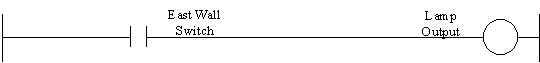
With the switch in the on position, the controller will see the input and activate the output to a lamp. The above is referred to as a rung of logic. Below is an example of a typical 3way switch for room lighting. The lines connecting the two sets of conditions together are referred to as a "branch".
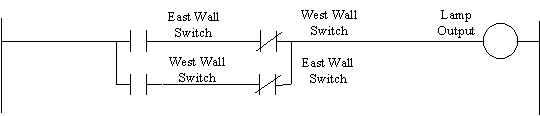
The conditions in the above example rung of logic states … "if (east and not west) or (west and not east) wall switch input, then output to the lamp." the first condition is (east and not west), the second condition branched with an "or" condition is (west and not east).
What are some typical applications in an industrial environment system?
Bin95: The most common application is for individual machine control but can range to full plant control linking several plcs together. On a particular machine, speed, options, safety, operator interface, pneumatic, hydraulic, electricity are some items that may be controlled. PLCs have several different types of input and output cards depending on the type out interface desired. All machines, room temperatures, power monitoring, even security can be joined by linking several PLCs. These can then be displayed and controlled by a single graphical user interface (GUI) or a standard personal computer.
What is a sequencer and how is it represented in a ladder diagram?
Bin95: This question jumps from the basics of the last two questions to an advanced topic, too complex to go into detail here. A sequencer can be used for diagnostics, or control when a machine operates within a set sequence of events. An example of a set sequence of events would be… the air blows off a mold, the mold closes, high pressure is engaged, and if the temperature is ok, injection cylinder pushes the material in mold, timer times up, mold opens. Then the cycle would start all over again.
How a sequencer is represented in ladder logic would depend on particular plc and associated software. In Allen Bradley, they use three sequence instructions. One to load sequencer, one for input conditions, and one for output conditions.
The general gist is when control sees a set of various pre-defined inputs, the sequencer will output a pre-defined set of outputs.
PLC direct software has an automatic conversion from ladder logic to sequential logic. This is not the same as described above. what their windows based software does is convert the ladder logic into a flow diagram, using real-world outputs for each block in the flow diagram. The most excellent way we have seen to quickly understand what makes what work. They are also the best price.
What is a time delay relay and how is it represented in a ladder diagram?
Bin95: There are two types of time delays, "delay on" and "delay off".
Delay on: a timer that starts to time when a rung goes true (all conditions met), and times up when rung is true for a preset amount of time.
Delay off: a timer that starts to time when a rung goes false (not all conditions met), and times up when rung has been false for a preset amount of time.
You can use the timer's "timed up" bit, or use it in it's inverted state "not timed up", for either timer type. Between the two timer types, you can create any kind of time-related relationship to input/output conditions occurring.
The way a timer is represented depends on the software used for each particular brand of plc. The basic elements are the preset, and the increment values. If the increment value is set to .01 then a preset of 100 equals 1 second.
How can i apply a timer, sequencer, adder, subtractor, multiplier, divider, and converter in a ladder diagram?
Bin95: Hire an engineer and specify what plc you want it programmed for, ha! it's really a bit much to write the ladder logic for all these items. We can give you an example of most though. From the combination of examples you requested you may be looking for an example of how gate logic would look, converted to plc logic. Advanced PLCs such as ABs PLC 5 allows you to type formulas directly into the ladder logic. Values are stored in memory locations called "integers".
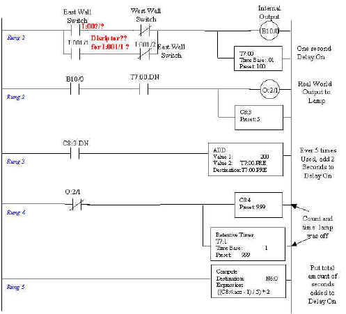
The example above is a simple 3-way circuit for house lighting. With a few extras just for discussion purposes. This is not a practical logic design and has no useful application. (Unless at some point in time you don't mind waiting for minutes for a light to come on after you actually switch it on. Ha!)
Rung 1: "If (east and not west) or (west and not east) wall switch input, then output to the internal memory (b10/0)." the first condition is (east and not west), the second condition branched with an "or" condition is (west and not east). Paralleled with the output is delay on timer t7:00, which will time up after rung is true (above conditions are met) for 1 second.
Note: i:001/1 is used on some switches, and description such as "west wall switch" is used on other switches in this rung. This is intentional so you can figure out what i:001/x (input address) is associated with which descriptor.
Rung 2: If the internal output is true (on) and the timer t7:00 is timed up (t7:00.Dn), then a real-world output will turn light on. Paralleled with the output is counter c8:3, which will output after rung is true (above conditions are met) 5 times.
Note: In this PLC logic software, timers and counters use extensions on their address to identify different functions of them. tx:xx.Dn = done bit, tx:xx.acc = accumulated value, tx:xx.Tt = timer is timing. cx:xx.Dn = done.
Rung 3: If counter c8:3 is done (light turned on 5 times) then add 200 (2 seconds with a timing base of .01) to the preset of timer t7:00. After the first 5 times, the light is switched on, the new delay-on time will be 3 seconds. So the more the light is used the longer the delay on will become, thus extending the life of the bulb.
Note: Some plc software will require you to use integers (like n6:02) to do addition subtraction, and the use a "move" instruction to place the results in a timer's preset.
Rung 4: If the output for the light is not on, then output to counter c8:4 and retentive timer t7:1. We used the real-world output to show they can also be used as conditions. We inverted it just to show an example of not active bit. The counter will count each time the circuit is turned off until it reaches 999. This count will be one more than how many times the circuit was turned on.
Note: the timer is a retentive timer that keeps it's value during power down, and would have to be manually reset. The time base on the timer is 1 second.
Rung 5: This rung is unconditional, therefore activates computational output (does the formula) every scan cycle. The formula takes how many time the circuit has been turned off (counter c8:4), and divides it by 5 to calculate how many times 2 seconds have been added to the delay on preset t7:00, by counter c8:3. Then the formula takes the previous calculation and times it by 2 to calculate the total amount of seconds that have been added to delay on timer preset. This final calculation is put in memory location n6:0.
Note: We minus 1 from the number of times the circuit is turned off, to get the number of times the circuit has been turned on.
Well, that’s it, in a nutshell. I hope all our readers get some value from this.
Visit the pick of the month link at ...
Troubleshooting PLC Control Circuits training software.