
- Home >
- schematic diagram
EZ Schematics: Electrical Schematic Drawing Software
Easier to use electrical schematic software with more accurate NEMA symbols.
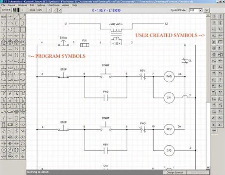
EZ Schematic Diagram
This EZ Schematic Diagram Software is electrical schematic software made easy to replace drawing electrical diagrams and schematics on a napkin at the dinner table. Yet functional enough to update drawings for electrical systems or a house wiring diagram, etc. Includes NEMA, IEC, and Electronic symbol libraries, as well as the ability to create your own symbols.
What sets this software apart from others? EZ Schematics is designed for quick maintenance drawing updates, with familiar NEMA symbols and a lower cost than full electrical engineering CAD suites.
EZ Schematics Standard features
This electrical diagram software is designed to allow maintenance, electricians, and engineers to easily update electrical diagrams and easily print out a professional-looking electrical schematic or wiring diagram. Instead of just scribbling on original electrical schematics or wiring diagrams. Designed to be much easier to use than typical electrical CAD software and as quick as jotting down electrical schematics and wiring diagrams on notepaper.
It comes with the electrical standard NEMA Symbols and IEC Symbols in the exact proportions you've grown used to and are comfortable with. With the snap feature, symbols are placed in precise locations resulting in a professional document you would be proud to place your name on. (Also comes with an Electronic Symbols library.)
Are you a field technician? Don't have time to learn new software? Unlike typical electrical CAD software, EZ Schematics is much easier to learn and quicker too!
One of the many reasons this electrical schematic software is quicker is that it automatically orientates the symbols the way you would normally use them (unless you opt not to), in contrast to other electrical schematic software that requires you to rotate each symbol after placing it in an electrical drawing.
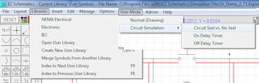
Bonus: 3 built-in circuit simulations for learning purposes. See the voltage change after you click on push button symbol or after timer times up in some circuit simulations.
Try or order EZ Schematics Standard
Click to download free EZ Electrical Schematic software trial , order unlock code for it below ...
Or you may consider ordering the EZ Schematics Pro. The Pro version includes a hydraulics library so you can draw hydraulic schematics too, and much more.
Electrical diagram drawing tip
Highlight parts of the electrical schematic (diagram) in color to demonstrate the principle of voltage potentials. This gives the end user a visual concept and understanding of the voltage differences (voltage potential) throughout the circuit. Now the circuit becomes more dimensional in the sense that it's not just a black-and-white schematic (diagram), but rather a more dynamic illustration. See the example below drawn using this EZ Schematic software. In this case, all of the high side voltage (120 with respect to neutral), is displayed in red. The low voltage (neutral) is represented in blue.
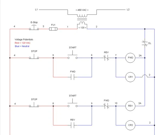
Electrical Diagram
Related drawing software and training
EZ Schematics Pro edition.
Electrical Troubleshooting (Interactive training via circuit simulation software.) |
EZ Schematics Standard: product and schematic FAQs
What is the difference between a schematic and a wiring diagram?
A schematic explains how a circuit works using symbols and electrical connections; component positions usually do not match the machine. A wiring diagram emphasizes actual connections, terminal identification and, where shown, physical locations. In industrial maintenance, use the schematic to trace control logic and the wiring diagram to locate and connect devices. EZ Schematics Standard can draw either type of diagram.
What do the dots and lines mean, and what if lines cross without a dot?
Lines normally represent conductors or electrical connections. A filled dot usually marks a connected junction. Crossing lines without a dot usually indicate no connection; some drawings use a bridge or jump instead. Older drawings and different conventions can vary, especially at T-junctions, so check the drawing legend and terminal or wire references before interpreting a connection.
What is the best software to draw industrial electrical schematics?
The best choice depends on the work. For beginners, occasional users and maintenance technicians updating or digitizing existing schematics, EZ Schematics Standard is a practical, lower-cost choice with a smaller learning burden than full engineering suites such as AutoCAD Electrical, SOLIDWORKS Electrical or EPLAN. Those suites suit larger projects requiring broader engineering automation and documentation. Choose EZ Schematics Professional for hydraulic and pneumatic drawings, or Constructor when you need to simulate your own industrial control circuits.
Which symbol libraries come with EZ Schematics Standard?
The Standard edition includes NEMA, IEC and electronic symbol libraries, plus the ability to create your own symbols. It also provides snap placement and automatic symbol orientation. Hydraulic and pneumatic symbol libraries are features of EZ Schematics Professional.
Can EZ Schematics simulate the circuits I draw?
EZ Schematics Standard includes three built-in circuit simulations for learning, where you can observe voltage changes as example push buttons or timers operate. These examples are not a general simulator for every drawing you create. For drawing and simulating your own power and control circuits, see Constructor.
Is EZ Schematics Standard free?
The download is a free trial. A paid unlock code is required for the full software; the single-user Standard edition is $149. Use the trial to evaluate the software before purchasing.
Choose the software for your task
For electrical and fluid-power documentation, see the EZ Schematics Professional circuit diagram maker with hydraulic and pneumatic symbols.
To draw and simulate your own industrial power and control circuits, see the Constructor 16 electrical circuit simulator.