Industrial Maintenance Technology Guide
- 1. Engineering Principles for Maintainers and Operators.
- 1.1. Work within the design limits
- 1.2. Force transmission
- 1.3. Stress in materials
- 1.4. Clearance, fits and tolerances
- 1.5. Bending stress
- 1.6. Torque stress and combined loads
- 1.7. Metal fatigue failure
- 1.8. Lubrication
- 1.9. Vibration
- 1.10. Chemical and material compatibility
- 1.11. Corrosion
- 1.12. Fluid flow
- 1.13. Cavitation
- 1.14. Welding metals
- 1.15. Welding plastics
- 1.16. Heat transfer
- 1.17. Bearing isolation and protection
- 1.18. Electric motors
- 1.19. Process control and monitoring
- 2. Equipment Maintenance Best Practice.
- 2.1 Creative disassembly
- 2.2 Bolting and gaskets in flanged connections
- 2.3 Threaded connections
- 2.4 Chain and sprocket drives
- 2.5 V-belt and pulley drives
- 2.6 Mechanical seals
- 2.7 Soft-foot distortion
- 2.8 Shaft alignment
- 2.9 Pneumatic valve actuators
- 2.10 Process control valves
- 2.11 Isolation valves
- 2.12 Roller bearings
- 2.13 Oil cleanliness
- 2.14 O-ring seals
- 2.15 Gear box drives
- 2.16 Gland packing
- 2.17 Vibration control
- 2.18 Non-destructive testing of welds
- 3. Types of Maintenance Philosophies.
- 4. Maintenance Management and Asset Management.
- 5. Fault Finding and Troubleshooting Check Lists

Now free here online as the industrial maintenance technician's guide App.
Authored and edited by Mike Sondalini B Eng. (Hon), MBA
ISBN: 0-9750232-1-7
Copyright © 2003 - 2025 Business Industrial Network
All rights reserved. No part of this publication may be reproduced, stored in a retrieval system or transmitted in any form or by any means, electronic, mechanical, photocopy, recording or otherwise, without prior permission of the copyright holder.Because the authors, publisher, and resellers do not know the context in which the information presented in the book is to be used they accept no responsibility for the consequences of using the information contained or implied in any articles.
To run a process, plant, or equipment well one needs to know the engineering that the designer used. This free online industrial maintenance technician guide will take maintenance mechanics, maintenance tradesmen, and process plant operators a long way toward understanding the key engineering used in their process, plant, and equipment. It will help its readers to run and maintain plants and equipment better than they have ever done before.
If you would like to reference this guide offline, and/or print copies for your maintenance, operators, or students in your facility, you can purchase a PDF version of this guide at the bottom of this page.
1. Engineering Principles for Maintainers and Operators.
1.1. Work Within The Design Limits
Once equipment or a process is allowed to run outside it’s design limits it will fail quickly. Some operators and supervisors may not realize that, but most industrial maintenance technicians do. The only way to get long-lived, well operating plant and equipment is to keep its individual components working within their service limits throughout their life.
The best way to guarantee long equipment life and reliable operation when in service is to run and maintain plant items exactly as the item’s designer planned for it to be done.
An operator and maintainer’s duty is to know the design limits of their process equipment and keep it within the acceptable design conditions. They need to know the engineering of their equipment so that they can operate and maintain it in the right ways to keep it working as designed.
Find out how the designer wanted it done. Read the manuals and understand exactly what to do, especially why it is done that way. Make the knowledge known to everyone that uses or maintains the equipment, make sure it becomes standard operating practice and make sure that it is never forgotten by anyone. This approach will give you confidence that your plant and equipment will work properly all its life.
Equipment, machinery and processes used in industrial plants and facilities are built to known, well-understood engineering principles. The process and equipment designer uses them to create equipment, machinery and processes. The designer expects that the operators and maintainers responsible to run the plant, processes and equipment operate and maintain them so that they perform exactly as he they were designed to work.
When the designer selects the materials and methods of transferring power and forces through equipment he works within the material’s design limits, chemical compatibility, thermal expansion allowances, fits and tolerances and the like. When the equipment is taken beyond the abilities of its design it is operating outside the expected duty and outside its limits of safe service. The equipment can fail at any time under those totally unwanted and unplanned conditions.
For example the designer assumes that bearings will be lubricated exactly as the bearing manufacturer states they are to be lubricated. That they will not experience forces greater than they were designed to take. Another example is that the designer expects wearing parts to be replaced when their operating life has come to an end. He has to make these assumptions to be able to build his design for a reasonable cost using the materials available.
A process, plant or equipment operator and maintainer has the job of nurturing their plant and equipment so that it operates within the service limits set by the designer. If the equipment runs outside of those limits the problem must be corrected quickly and brought back into tolerance or else it will fail and breakdown. When the plant stops too often the business will lose money, it will lose customers and eventually employees will be put out of work.
1.2 Force Transmission
A structure is anything solid. When an object is solid it can take a load. When a load is applied to a structure it is stressed. The type and extent of the stress depends on the amount of load, the position of the load, the direction of the load, the shape of the structure and the properties of the material in the structure. A structure must be designed to take all the stresses created by the loads it is to carry.
A load cannot be carried in open space but only through a solid structure. An applied load is transmitted through the structure as a force. The force produces stress in the material as the structure reacts against the force to retain its shape.
There are three common types of stress produced by the application of a load. The first is a tensile stress and is produced when a force pulls a thing apart. The second is a compressive stress and results when a force is acting to squash a thing together. The third type of stress is a shear stress and is the result of a force producing a tearing action through the object. Figure No. 1 shows examples of the three types of stress.
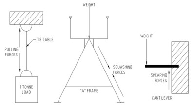
A force acting on a solid produces stresses in the solid. Stress is defined as the force acting on an area square to the direction of the force. Its formula is
Stress = Force / Area (Newton/meter x meter)
Its unit of measurement is the Pascal (Pa) and one Pascal equals a force of one Newton over one square meter of area.
The formula presents three options to handle stress. The first is to reduce the size of the force, the second is to increase the available area over which the force can act and the third is to use materials with a higher breaking stress than the stresses the load produces.
The position and direction of the force determines which stresses occur. Shear stress causes the greatest problem in engineering materials. In selecting the type of material and its size for a structure all three stresses have to be determined. Once the maximum amount of each type of stress is know the correct material type and cross-section can be chosen to handle the stress without failing.
Handling applied forces
If maintenance and engineering are faced with situations where parts and equipment are failing from stresses produced by high loads or fatigue situations, look at ways to increase the area over which the load is applied. Sharing the force over a greater area will decrease the stress in the material.
Where the cross sectional area cannot be changed then substitute a material of higher breaking strain and suitable corrosion resistant properties.
1.3 Stress in materials
Stress occurs when forces pull (tension), push (compression) or act in combination on a material. When a force is applied the material reacts by distorting to counterbalance the force. A greater force will cause a correspondingly greater distortion until the item breaks.
Stress & strain in materials under loads
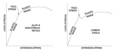
Stress is the force applied per unit of cross-sectional area square to the force. Strain is the amount the material deforms from the unloaded state when the force is applied. It represents a proportional change in size. When a force is applied to a metal deformation occurs and it is strained. The more the force, the more the deformation (strain). This relationship is recognized in Hooke’s Law and is shown in Figure 1 for two types of metals.
Figure 1 indicates that metals have an elastic region where load and strain are proportional (a straight line on a graph). In this region the metal acts like a spring and when the load is removed the deformation (strain) reduces and it returns to its original shape. If instead the load increases, the strain (deformation) rises until a point is reached where the metal can no longer sustain the load and it yields. The yielding can be gradual as in the left-hand plot of Figure 1 or it can be sudden as in the right-hand plot.
At the molecular level
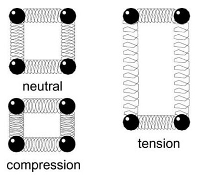
The behavior of metals under load is a result of their atomic arrangement. When a material is loaded it deforms minutely in reaction to the load. The atoms in the material move closer together in compression and further apart in tension. Consider the atomic bonds as being springs separating the atoms as shown in Figure 2. The springs are squeezed together in compression and pulled when in tension. The amount an atom moves from its neighbor is its strain. As a force is applied the atoms change a proportionate distance.
Effect of applying loads on a material
A load applied to a metal is distributed along the atomic rows in the crystals. The crystal structure is not perfect, often a row of atoms will stop mid crystal, and a gap is created in the atomic structure. These gaps act as huge stress raising needle-like points known as dislocations. At the end of the rows forming dislocations the force is transferred to the deformed bonds with neighboring atoms. Fewer bonds now carry greater loads and eventually fail as the force increases. As each atomic bond is broken and then remade with the next atom the dislocation moves an atom. Eventually the dislocation makes its way to the outside of the crystal. If sufficient dislocations accumulate at the crystal boundary the crystal separates from its neighbor. When enough dislocations gather the material fails.
Reducing stresses
It is fortunate dislocations are present in metals for they allow us to form and shape metals using less energy than if they did not exist. Their presence requires us to be aware of how to prevent them from accumulating at grain boundaries so that they will not eventually lead to the failure of the item.
Heat stress relief.
Allows crystals to develop properly in the metal.
Sufficient cross section.
Provides adequate amount of metal for the load.
Rigid while flexible construction
Provides multiple paths for the force to be transmitted through a structure.
Use generous contours.
Round off all sharp steps on shafts; make big radius on fabricated bends; change cross sectional shapes gradually.
Smooth surface finish.
Remove surface cracks by polishing; punch holes out instead of drilling; ream drilled holes.
Remove sharp corners in penetrations.
Radius all sharp stress-raising corners.
Table 1 shows some of the common methods used to reduce the influence of dislocations.
Also review the 5.1 Shafts Breaking Troubleshooting Examples table.
1.4. Clearance, fits and tolerances
A designer starts creating a new design by first drawing it on paper. When he draws a straight line he makes the assumption that the line is drawn perfectly straight. Unfortunately the real world is not perfect. It is imperfect. So the designer allows for imperfection by providing a small range of acceptably close values that he will allow in his design. He has introduced a degree of tolerance, or an acceptable amount of imperfection, that his design can work within.
Clearance
Equipment is designed so that parts have either a gap between them so they can move separately to each other or they are firmly in contact and do not move relative to each other. The gap or lack of it, between the hole and shaft is called the clearance. Clearance is determined by the size difference between the parts. Fits and tolerances are used to specify the size range of parts.
Fit
The types of fits have been given names. They range from an interference fit, where the parts are purposely made to be forced together. This fit can be further described as heavy through to light interference. Whereas a clearance fit is for parts made to have a space between them. This fit can be further described as tight through to loose. Between these two fits is the transition fit where interference may or may not occur. The amount of interference or clearance is achieved by specifying the tolerance range for the parts possible sizes.
Tolerance
Because of gradual cutting tool wear and minute changes in the machine tool internals due to temperature changes and wear/movement of internal parts, machined items can not all be made perfectly to the same dimension. It is permitted to make the part to within a range of sizes. That range is called the tolerance on the dimension.
Selection of tolerances for a part is made after considering -
· the speed at which the part moves
· the applied loads and forces it must withstand
· the amount of vibration permitted
· whether grease or oil lubrication is used
· ease of assembly
· changes in size due to thermal expansion.
When tolerances are too loose parts rattle about causing vibration and wear. An oversized bore on a shaft coupling allows it to flop about on the shaft. At high speed the coupling is thrown about causing noise, vibration and shaft distortion. Bearing failure occurs well before time. Always machine parts to the proper size and tolerance for the application. These can be found in fits and tolerance tables.
Machine parts heat-up when operated and they expand and change size. If there is insufficient clearance when the parts have expanded they may contact, or loose contact or prevent sufficient lubrication thickness to develop. When parts make contact heat is generated and material is scraped off into the lubrication system. Eventually contamination and damage become severe and the machine fails.
Thermal growth of machine parts can also cause alignment changes. There have been occasions where a machine aligned when cold, goes out of alignment when at running temperature. Various parts have grown in length with the warmth of operation and contacted neighboring parts. The forces generated cause deformation and distortion.
Always measure & check the clearance
For maintenance to be certain sufficient clearance is available between parts for radial and axial thermal growth the dimensions of the parts must be measured and the clearance checked and recorded. Measure corresponding dimensions on each part with micrometers. The measurements are then subtracted from each other and the difference is the clearance when the parts are cold. In critical applications it is necessary to determine the growth in size when the machine is at operating temperature. The formula for thermal expansion is available from machinery handbooks. The growth in size is added to the ‘cold’ dimensions and the clearances again determined.
During machine disassembly and assembly the available gap between holes and shafts can be readily checked with micrometers. It is more difficult to check axial spacing. A simple method to check axial clearance is to insert plasticine between the shoulder and the abutting face and mount the parts fully. The plasticine is squeezed into the available space, the parts are again stripped down and the thickness of the plasticine checked with a micrometer. Only use enough plasticine so the parts still pull-up together as if finally assembled.
Make drawings and a record of the measurements taken from parts and keep the information on file. When the equipment is next inspected these records become the reference against which the parts are again checked and it will be easy to pick up evidence of new wear and distortion.
1.5 Bending stresses
If you were to hold a half-full pail of water in your right hand with your arm outstretched your muscles would start to ache. It would not be long before you would have to put it down because of the pain. Your arm was under stress. Equipment parts suffer the same sort of bending stresses and will break when they get too much.
Bending Stress in Machinery Shafts
Figure No. 1 shows three common situations of loaded round, rotating shafts along with the location of their high bending stress points. On the left-hand side is a cantilevered load such as the drive pulley on an electric motor. In the center is a uniform load such as on the head and tail pulleys of a conveyor. To the right is a point load such as occurs on the shafts carrying the gears in a gearbox.
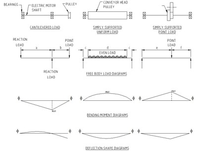
Each of the shafts can be analyzed and the bending stresses calculated. The highest stress is then checked against the allowable yield stress before it bends and the fatigue limits of the shaft material. The analysis determines if the shaft will meet its duty, or if a different size shaft or a different material with greater stress carrying ability is needed from that originally proposed.
The point of highest stress is found by drawing a bending moment diagram for the shaft. This is a graph showing the force multiplied by the distance along the shaft from a start point (datum). The size of the bending moment depends on the amount of load and the distance it acts from the datum. A load acting a long way from the datum produces bigger bending moments in the shaft than one acting closer to the datum.
Look for the point of greatest stress.
For single diameter shafts the location of the highest bending moment is also the point of highest stress. If the shaft is stepped with different diameters it is necessary to calculate the maximum stress along each diameter. The stress in a particular spot on a shaft depends on the shaft’s ability to carry the moment. For a round shaft that ability depends on the area available to take the load and the strength of the shaft material.
The ability to resist breakage depends on the shape and size of the shaft (Second Moment of Area) and the ability of the material to resist tearing apart (Young’s Modulus). If the shaft thickness is too little, or the shaft material is too weak, the shaft will bend or snap. Knowing the location of the maximum stress allows one to locate the point of likely failure in overload situations and so prevent breakage occurring in the first place.
Bending moments also cause deflections. The shaft bends under the combined effect of the loads. In simply supported situations the maximum deflection is at the point of maximum bending moment. This is also the point of maximum stress. By looking for the place where the shaft is forced furthest from its axis on simply supported set-ups, you can find the point of highest stress.
The greatest bending stress is on the outside wall of the material, with the outer surface of the bowed material in tension and the inner surface of the bowed material in compression.
Figure No. 1 also shows the deflected shape the shafts would take under the imposed loads. These deflections would normally be from a few 1/10ths mm to a few millimeters depending on the size and position of the loads, location of supports and the properties of the shaft. When wear occurs on rubbing parts, or shafts snap, it is very likely that excessively high bending stresses were involved.
1.6 Torque Stress and Combined Loads
Torque is the measure of twist produced by a force applied at a perpendicular distance from the point of twist. The sketch shows an 80 kg man standing on a one-meter long horizontal bolt spanner.
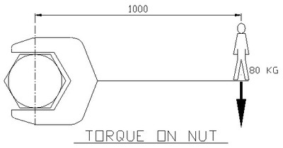
The man in the figure is applying about an 800 Newton meter (Nm) torque to the nut. If the spanner were 500 mm long (half the previous length) the torque would be 400 Nm and if it were 300 mm long, the torque would be about 250 Nm.
The size of the torque is directly proportional to the length of the lever arm. If the lever arm is longer for the same amount of load then the torque is greater than if the lever arm were shorter. The amount of torque can be changed by changing the strength of the applied force or by changing the length of the lever arm.
Location of maximum torque stress
As in the bending of shafts and beams, an applied torque will place the material being twisted under a stress that will produce a strain in the materials structure. The material reacts against the applied force by internally deforming the atomic structure until the atoms adjust to the load. If the load becomes greater than the atomic structure can handle the material twists apart.
A part under a torque load experiences the greatest atomic deformation (straining) at the outside surface of the material. The strain decreases toward the center. Torque fractures start from the outside and work their inwards to the center. A over-torque stress break on a shaft is easily recognized because the break face is at an angle to the axis of the shaft.
The amount of torque that a shaft can handle before failing depends on:
§ the stress limits of the shaft material. Material of greater stress carrying ability will take more torque.
§ the angle of twist. A small angle of twist causes less stress than a larger angle of twist.
§ the shape and thickness of the material. A 50 mm thick bar will take more torque than a 25 mm thick bar.
§ the length from the fixed end to the point of force application. A longer bar allows the torque stress to be distributed over a greater amount of material than in a short bar under the same load.
Combined Loads – When bending and torque occur together
In most industrial situation bending and torsion occur at the same time then a load is applied. For example when an electric motor drives a shaft through a gear box and a pulley, gear or sprocket is turned, the shaft carrying the pulley, gear or sprocket is both twisted as the shaft rotates and bent as the load being driven is taken up.
The combined stresses in the material act together at the same time. Their size is a straight addition of all the stresses acting at the particular point being considered. Depending on the arrangement and timing of the applied loads the stresses may counteract each other, with bending acting against torsion. In other situations the applied loads and the time when they act add together and greatly increase the stress at that point in the material.
When machine parts or drive shafts continually break or break once unexpectedly it is necessary to analyze the combined effect of the various stresses acting on it and determine if the material and the shape of the part were able to handle the combined loads on it.
1.7 Metal Fatigue Failure
Metal fatigue occurs when parts break at a weak point after a period of time in service due to cyclic forces producing fluctuating stresses. Knowing a part will be subject to fluctuating loads requires the designer to design the part for that condition. The part is designed so that the cyclic loads applied to it keep the relevant stresses within the material’s fatigue stress limits.
Theory of Fatigue Failures
The generally accepted explanation for the mechanism of metal fatigue is based on dislocation theory. Basically the theory says that the atomic arrangement in the crystals of a metal is imperfect and contains numerous missing atoms. The missing atoms create gaps, which cause massive stress raisers. When the metal is put under load the stress raising gaps shear their way through the crystal grains and collect together to make a microscopic crack. If the load fluctuates from a minimum to maximum near the metal’s load carrying limit new microscopic cracks expand out from the site of the first micro crack. Each crack is a stress raiser for the next one and they continue to develop until the remaining metal can no longer take the load and it fails.
Metal fatigue is directly related to the number of stress cycles undergone by a part and the level of stress it carries. Studies have shown that infinite life for a metal part is possible if the local stresses in the part are kept below known limits. Fatigue failures increase if parts have stress raising contours or stress raisers such as notches, holes and keyways are put into the part. There is also a relationship between a metal’s ultimate tensile strength and hardness and its ability to handle fatigue loads. The higher the tensile strength and hardness the more likely it will fatigue if it is subject to high fluctuating loads.
Stress Concentration Factors
Virtually all fatigue failures occur on the outside surface of a part where the combined stresses are highest. Fatigue failures start at stress concentration points or stress raisers. Examples are grooves, fillets, holes, threads, keyways, splines, welds, etc. The effect a stress raiser is directly related to the smallness of its radius. The smaller the radius of a stress raiser, the more focused and larger are the resulting stresses.
If problems from stress are likely, the designer has the choice of increasing part size, changing to a higher tensile strength metal or surface treating the part to greatly reduce the chance of fatigue cracks developing.
Surface Finish and Surface Microstructure Treatments
Since fatigue failure usually starts at the surface of a part where the applied loads produce maximum stresses, it becomes important to consider the surface finish and surface microstructure. When the surface of a part is under tensile stress, microscopic surface cracks are most likely to develop at stress raising locations. If the stress raisers were not present the part could sustain greater load. Alternatively, if the metal’s outer layer had higher tensile properties it would take greater stresses to nucleate a crack site. Great improvements in a part’s strength can be made by treatments that strengthen the surface material.
The less the roughness, the smaller the microscopic grooves and the larger the valley radius becomes in proportion to the height of the groove. Larger radii decrease the effect of the stress raiser and increase the fatigue stress at which a part fails. Polished, ground and machined surfaces are best. Forged and cast parts are worst due to poor surface finishes.
Recommended Practices to Increase Fatigue Life
When designing and making a part there are a number of factors to consider to get maximum fatigue life.
· Avoid sharp corners. Use generous radii to reduce stress concentration levels.
· Avoid abrupt changes in cross-section. Remove metal so there is a smooth transition between cross-sections.
· Make machined surface finishes as smooth as possible. Scratches perpendicular to the applied loads become stress raisers. Use fine emery cloth to polish the surface.
· Welding needs to be of good quality with no inclusions, gas holes (porosity) or worm holes. The weld fillet should have a nice contour and be completely filled.
· Welds alter the metallurgical properties of a metal (rapid cooling rates cause large grain growth) and the parent metal is weakened in the heat-affected zone (HAZ). The HAZ extends below the weld and fatigue cracks can develop under the surface. If the part is critically loaded it will be necessary to heat treat the HAZ to modify the metal’s microstructure.
· Surface treat to produce compressive forces or appropriate metallurgical properties in the outer layers of those parts which will be cyclically loaded at stress raising locations.
· Select materials with good fatigue resistant metallurgical properties. Use small grained, homogeneous microstructure, high tensile stress with some degree of ductility.
· If a part is scratched or has a machining mark, polish the defect down to its base and blend the sides into the parent part.
1.8 Lubrication
Clean, dry oil can extend equipment life between failure up to 8 - 10 times the normal operating life. Timken, the bearing manufacturer, reports that reducing water levels from 100 ppm (parts per million) to 25 ppm increases bearing life 2 times. British hydraulics research indicate that if solids contamination with particles larger than 5 micron (0.005 mm or 0.0002”) is reduced from the range of 5,000 – 10,000 particles per milliliter of oil to 160 – 320 particles, the machine life is increased 5 times.
How contaminated oil destroys equipment
Dirty oil spells rapid death for hydraulic machinery and lubricated equipment. Fine tolerance equipment can have clearances between parts of 5 to 10 microns (0.005 – 0.01 mm, 0.0002” - 0 0.0004”). Solid particles larger than the clearance gap will jam into the space. The solid particles will further be broken-up and mangled while ripping out more material from the surfaces. In equipment with larger tolerances the oil film between parts can get as thin as 3 – 5 micron. Solid particles larger than the oil film will be broken up into smaller pieces and produce more solids contamination. Figure No. 1 shows a shaft in a journal bearing lubricated by oil. If the solid particles are larger than the oil film thickness and when they enter the bearing pressure zone at the bottom of the shaft they will tear into the metal, be broken up and make more particles that cause further wear.
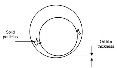
Solids suspended in oil are like grinding paste. They scour and gouge surfaces; block oil passages and makes the oil more viscous. The longer the oil is left dirty the faster the rate of failure. Even expensive synthetic oil is of no use if it is contaminated by solid particles. Though synthetic oil has better high temperature and surface tension characteristics than mineral oil all advantages are lost if the synthetic oil is so contaminated that it is destroying the machine. The only solution is to keep the oil clean by filtration.
Counting standard ISO 4406 -1999 is used internationally to rate solids contamination of oils. This standard classifies the cleanliness of oil and provides a basis to define acceptable solids contamination. It also means oil filters can be tested to prove their performance meets acceptable standards. Table No. 1 is part of the ISO 4406 method of coding the level of solid particles in an oil sample. The solid particle content of oil gets a classification that represents the number of particles of a particular size range.
ISO Scale
Particles per milliliter
Number
More Than
Less Than
22
20000
40000
21
10000
20000
20
5000
10000
19
2500
5000
18
1300
2500
17
640
1300
16
320
640
15
160
320
14
80
160
13
40
80
12
20
40
11
10
20
10
5
10
9
2.5
5
8
1.25
2.5
Table No. 1 Allocation of Particle Count Scale Numbers
Component
< 3000 psi
> 3000 psi
Fixed displacement pumps
Vane
17/14
16/13
Gear
17/15
16/13
Piston
16/14
15/13
Variable displacement pumps
Vane
15/13
-
Piston
15/13
14/12
Valves
Directional
18/15
17/14
Proportional
16/13
15/12
Servo
14/11
13/10
Table No. 2 Recommended Target Oil Contamination Levels
Where calibrated automatic counting devices are used to measure contamination; three scale-numbers are used to describe solids contamination. These are the 4 micron and larger, 6 micron and larger and 14 micron and larger. When the count is done by optical microscope two size ranges are used – the 5 micron and larger and 15 micron and larger.
For example oil solid particle contamination can be described as ISO 20/18/16. This would mean there are between 5000 and 10000 particles larger than 4 micron per milliliter sample. Also there are between 1300 and 2500 particles larger than 6 micron in per milliliter of sample and between 320 to 640 particles larger than 14 micron. If a two scale number is used the contamination result could be 18/16. In this case there are between 1300 and 2500 particles larger than 5 micron in per milliliter of sample and between 320 to 640 particles larger than 15 micron.
Wear in moving equipment such as gearboxes, pump bearings and hydraulic rams is a function not only of how much work the item does but how we treat the lubricant at commissioning and during operation. Starting with the commissioning, a survey quoted in an SKF publication of drummed fresh gearbox oil found surprising levels of particulate contaminants. The action to cover this problem (especially at remote mine sites) is to filter your oil prior to charging a piece of equipment.
Oil filtration
This leads to the question of what sort of filter? Some filters are wire mesh or paper based, others are made from synthetic fibers locked in position with epoxy resin. Another aspect of the quality of the filter is the fiber size with respect to the gap size. Clearly a filter with fine fibers for a particular pore size will have more pores and will last longer. So cheapest may not be best. If you want extremely low wear rates and long equipment life the evidence indicates that oil needs to be filtered down to sub 5 micron size and preferably down to one micron size. Care needs to be taken that the filter does also not remove any solid additives, such as graphite, in the oil. Additives dissolved in the oil will not be removed unless the additive is attached to a solid particle.
Oil filtration can be done under full oil flow or with by-pass flow or offline when the machine is not operating. There are several filter types such as pleated paper and wrapped fiber cord. In all cases the filter must capture a large proportion of greater than 5-micron particles if it is to clean the oil.
Filter performance
The correct way to measure filter performance is by use of the Beta Rating. It is a ratio that measures the number of particles entering a filter to the number leaving the filter. It is an accurate way to measure true in-service performance. Nominal filter micron size ratings from manufacturers are arbitrary and so meaningless. And absolute filter micron size ratings are unreliable since the softer particles in the oil can be squeezed through the filter and reappear as contaminants. When filters are tested, they measure the particles going in verse those coming out. The ratio, the Beta Rating ‘b’, and its subscript represents the particle size it was tested at. Filters having a b6 rating of 75 or better are suitable for filtering gearbox oil. This code means that 74/75 of the particles of 6 microns or bigger is removed.
Many original equipment manufacturers have accepted the indisputable evidence from numerous field and laboratory trials that oil cleanliness has a major effect on wear within their equipment. Some of them are now specifying how clean must be the oil used in their equipment if warranty claims are to be honored. For example Caterpillar specify new oil to have a particle count of ISO 16/13. If new oil is above this level of contamination they will not warranty their equipment. When new oil from a leading international oil manufacturer was tested before putting it into new Caterpillar equipment the solid particle contamination was found to be 17/14. This was new oil from a never previously opened container. In this case the new oil had to be further filtered to bring it to below the required specification.
Table No. 2 is a list the recommended target oil contamination levels for close tolerance equipment from a survey of hydraulic oil equipment and oil filter manufacturers.
So what do the elite performers do? They monitor the oil and pay attention during the commissioning phase. A study by SKF on gearboxes showed that hard particles went from 100 on startup to about 8000 after 5 hours, to 10,000 per ml after 38 hours. So change or filter your oil in the early stages after commissioning. Then look after it during operation, because when metallic particles, sand, dirt, etc bridge component clearances, the ‘little blighters’ are going around grinding and grooving their way through the circuit and the machine parts. The more of them that there are - the more damage is being done. It’s obvious isn’t it! And we need to act accordingly?
If you would like to reference this guide offline, and/or print copies for your maintenance, operators, or students in your facility, you can purchase a PDF version of this guide below.
On to 10 more Principles of Applied Engineering ...

