Fault Finding and Troubleshooting Examples
5. Fault Finding and Troubleshooting Examples.
5.1 Shafts breaking
As well as using the troubleshooting examples below, read the notes in the sections on Force Transmission, Stress in Materials, Bending Stress, Torque Stress and Combined Loads, Metal Fatigue Failure and Welding Metals.
Observation
Possible Causes
Remedy
Shaft is bent in the center or broken in the center straight across the axis and no thinning from corrosion.
High bending loads causing shaft deflection.
- Remove material build-up causing deflection.
- Increase the diameter of the shaft and provide more cross-sectional area further from the axis.
- Support bearing at point of high deflection.
- Decrease forces causing the deflection.
Shaft has broken at a machined shoulder and ‘beach tide marks’ can be seen on the break faces.
Shoulder radius is too sharp and has created a stress raiser under fluctuating loads and caused a metal fatigue failure.
- Provide a more generous shoulder radius.
- Change to a material that has a higher yield stress.
Shaft has broken at an angle across the axis and there is evidence of a twisted tear.
Torque overload due to a jammed component.
- Increase the diameter of the shaft and provide more cross-sectional area further from the axis.
- Change to a material that has a higher yield stress.
5.2 Bearings Failing
As well as using the troubleshooting examples below, read the notes in the sections on Lubrication, Bearing Isolation and Protection, Oil Cleanliness and O-ring Seals.
Observation
Possible Causes
Remedy
Bearing runs at high temperature.
Too much, too little lubricant.
- Check exactly how much lubricant is being fed to the bearing and how often then compare that to the recommendation from the bearing manufacturer.
Wrong grease for the application.
- Check actual environment of the bearing and bearing housing and confirm with the lubricant manufacturer and bearing manufacturer that the lubricant will handle those conditions.
- Check the loads taken by the bearing and its rotational speed and confirm the lubricant is the right one for the load situation.
Bearing collapses.
Bearing has been contaminated with dirt, water, chemicals or other contaminant.
- Protect the bearing from ingress of contaminant with better sealing methods.
- Change the bearing out on a time basis before it fails.
Wrong grease for the application.
- Check actual environment of the bearing and bearing housing and confirm with the lubricant manufacturer and bearing manufacturer that the lubricant will handle those conditions.
- Check the loads taken by the bearing and its rotational speed and confirm the grease is the right one for the load situation.
Wrong bearing selected for the application.
- Determine the working conditions and design requirements of the bearing and check the bearing selection with the bearing manufacturer.
Bearing is noisy.
Bearing has been contaminated with dirt, water, chemicals or other contaminant.
- Protect the bearing from ingress of contaminant with better sealing methods.
- Change the bearing out on a time basis before it fails.
Bearing is being forced out of shape by shaft expansion.
- Ensure the shaft has room to grow or shrink with temperature change and one end bearing can move with the shaft.
Bearing housing is distorting.
- Confirm no ‘soft foot’ problems are present.
- Confirm the bearing housing support frame is not distorting.
Too little lubricant.
- Check actual environment of the bearing and bearing housing and confirm with the lubricant manufacturer and bearing manufacturer that the lubricant will handle those conditions.
5.3 Mechanical seals failing
As well as using the troubleshooting examples below, read the notes in the sections on Mechanical Seals, Bending Stress, Soft Foot Distortion, Shaft Alignment and Vibration.
Observation
Possible Causes
Remedy
Leak from seal
Pressure hammer.
- Slow down speed of closing valve.
Dirt caught between seal faces.
- Use utterly clean assembly practices.
- Remove pressure hammer problems.
Product build-up on seal faces.
- Do nothing if chemical is not dangerous or harmful.
- Install barrier fluid system at higher than stuffing box pressure.
Seal faces were run dry and burnt.
- Prevent loss of product or barrier fluid around seal.
- Shutdown equipment on detection of fluid loss.
Preload lost on seal faces.
- Locking screws have loosened and seal housing slipped along shaft.
- Internal springs clogged with material build-up.
- Internals have corroded.
Installation errors.
- Seal faces incorrectly preloaded.
- Seal faces damaged or scored.
Slender shaft, long overhang.
- Minimise the shaft slenderness ratio (L3/D4) to 75 or less in inches or 2.5 in metric.
Shaft alignment out of tolerance.
- Align shaft axis to 0.05 mm or 0.002” using dial indicators or laser.
Chemically incompatible parts.
- Select proper face, hardware materials and elastomers.
Equipment vibration.
- Balance rotating parts.
- Tighten base plate bolts.
- Install larger mass base three times the equipment mass.
Equipment is distorted.
- Remove pipe stresses and insure mating faces are in alignment.
- Check both stationary and running soft foot and rectify problems.
Pump running at off duty conditions.
- Remain in the window of operation for the pump.
5.4 Flanges leaking
As well as using the troubleshooting examples below, read the notes in the sections on Chemical and Material Compatibility, Bolting and Gaskets in Flanged Connections and Threaded Connections.
Observation
Possible Causes
Remedy
Leaking flange
Gasket material incompatible.
- Check gasket material selection.
Gasket is too thick.
- Use thinnest gasket possible.
Bolts are loose.
- Use high tensile bolts and nuts.
- Tension bolt to 75% of yield stress in proper sequence.
- Use same bolt size and specification throughout.
- If nuts bind on bolt threads get a new bolt and nut to the right specification.
Pipe work was over-pressured.
- Install pressure relief to a safe place.
Corrosion attack.
- Protect bolts from chemical and environmental corrosion.
Flanges are out of square.
- Cut off flanges and replace them square to pipe and each other.
- Remove any pipe misalignment by removing and installing the pipe again.
Flange faces are dirty, distorted.
- Clean off all old gaskets so face is like new.
- File burrs of flange faces so faces are flat.
- Replace or re-machine faces that are deeply scored or corroded.
5.5 Troubleshooting Methods Examples
Divide and Conquer Troubleshooting Method
The divide and conquer troubleshooting method is the most simple and common troubleshooting and fault finding method. This approach is to divide the equipment, machine, production line, system into sub-systems. Preferably only 2 systems. Once you determine the sub-system the fault is in, then if appropriate, divide that sub-system into even small sub-systems. In electrical troubleshooting, after the divide into sub-systems, the tracing back troubleshooting method is used.

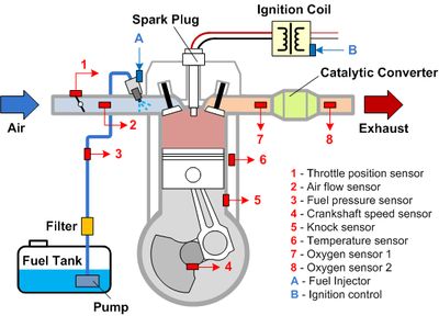
An example of this approach that I have seen occurred when a rental car stopped running. The road service auto mechanic started off with the divide and conquer troubleshooting method. First, he checked the electrical system by removing a spark plug and turning the ignition key. The car cranked over, and the spark plug fired. This test proved the electrical system functioned properly because a spark was evident at the spark plug.
He then checked the fuel supply (2nd part of the divide method). Here he removed the rubber fuel line into the carburetor and cranked over the engine. However, no fuel was ejected. Moving back along the fuel system (Tracing back method), he removed the connection to the fuel pump outlet and cranked the motor. Again, no fuel was evident. He checked the fuel level in the fuel tank, and it was plentiful. Removing the fuel line into the fuel pump resulted in fuel spilling out on the ground. He had just proven that the fuel pump was broken because the fuel at the inlet was not discharged from the outlet.
RECOMMENDED APPROACH TO FAULT FINDING
- Divide the equipment into logical systems.
- Test each system's functions to specification.
- Test each component in the failed system operates as it ought.
Often in industrial equipment and systems, the first use of divide the system into sub-sets troubleshooting methods is deciding based on symptoms, whether to send a mechanic, or an electrician to troubleshoot it.
5.6 Electrical Troubleshooting Examples
The exclusive content in this section is not available in the print version. It is likely this section will grow as time goes on.
Above we explored some mechanical troubleshooting examples, now we will explore some electrical troubleshooting examples. Electrical troubleshooting can often be easier and quicker than mechanical troubleshooting. This is due to the electrical control circuit's inherent binary nature. (A 1 or 0, true or false, yes or no) The first divide into sub-systems to troubleshoot is to decide to start with inputs or outputs based on the symptoms and preference. Once you decided which test point (input or output) to start with, it is just a simple matter of tracing backward with electrical test equipment looking for an incorrect reading. Most commonly the test equipment is a VOM?, second an Amp probe, rarely an oscilloscope.
The physics of troubleshooting
Always keep on the top of your mind, the physics in relation to failures. Because of wear, mechanical components have the highest probability of failure. Followed by electromechanical components like relays, then followed by heat with is proportional to the current (high amperage components). Solid-state devices (like digital) are the least likely to fail, as they typically are low voltage, which equates to low current, and there are no moving parts (mechanical) in solid-state devices.
Physics of Troubleshooting Examples
(In order of most likely to fail to least likely.)
Attribute
Electrical Control Example
PLC Control Example
Mechanical
External to electrical control
External to PLC control
Electro-mechanical
Ice Cube Relay
Relay Output Card
High current
Motor Starter
Triac Input Card
Low current
Sensor
Analog Input Card
Solid-state
Solid-state Timer
PLC Processor
The environment can be an exception to the general rules. The environment can change the basic order above. A couple of examples, in a foundry, the metal dust causes
the backplane to fail more frequently. In the machining industry, penetrating fluid getting into sensors causes input cards to fail more than output cards because the liquid causes the input card to sink more current than designed to. In wire manufacturing were a lot of high voltage insulation testing is going on, CPUs fail more often because the control voltage for PLC does not have a line filter in line with it. etc.
Other variables that affect the failure rate are improper design, like not allowing the 20% extra when calculating relay card or power supply current, etc etc.
Above and beyond physics, what is a more probable cause of failure than even Mechanical causes? Human Error (sometimes Root Cause Analysis must be performed to reveal this fact.)
Need to practice your electrical troubleshooting? Try our free online Industrial Electrical Troubleshooting Simulator Game.
Just starting out, try our Troubleshooting Training Certificate Course with real-world simulations.
PLC Troubleshooting
So generally speaking the physics discussed in the previous section applied to PLC hardware failure is as follows. Once again highest probability of failure to least likely to fail.
- External to the PLC
- Output Cards
- Input Cards
- Power Supply
- Backplane
- CPU Processor Module
'PLC Troubleshooting' can mean two different things to those seeking knowledge on the topic. To some, they are meaning troubleshoot the PLC itself, but to most, it means using the PLC to troubleshoot the machine/industrial system. The reason most people are referring to using the PLC to troubleshoot is that a PLC is built so reliably, the PLC is the least likely component to fail in an industrial control system. Just like troubleshooting electrical is often easier and quicker than troubleshooting mechanical problems, the same is true about using PLCs to troubleshoot equipment as compared to using a VOM to troubleshoot equipment's electrical. Using the PLC as your test instrument is much easier and quicker to troubleshoot than physically going to various points in the machine, opening electrical covers, and testing each point with a VOM.
If you have used a VOM to troubleshoot before or you used the free online electrical troubleshooting simulator game linked to above, you have a sense of what it takes to trace back thru a circuit. Also using a meter to trace back has other variables that slow down the troubleshooting process. There are safety procedures and risk, reliability issues too. for example, an oxidized wire screw could result in incorrect reading on the meter, dead battery in the meter, missing electrical schematics, wrong meter settings, etc. As you will see below, using a PLC to trace back thru the circuit, greatly simplifies the process, removing all the time-consuming variables that come with meter tracing of a circuit previously mentioned. It is simple as looking on a computer screen and see what contact/device is not highlighted green. The PLC makes it so simple, even a non-electrician can troubleshoot complex equipment in most instances.
But don't throw your meter out, once you use the PLC to trace the problem to an individual component, you will need the meter to test that component like a switch or solenoid. Once the PLC isolates the problem to a single real-world input or output, you will take off your PLC technician hat and put on your electrician hat to determine why the component is not working and what is needed to repair it.
PLC Troubleshooting Example

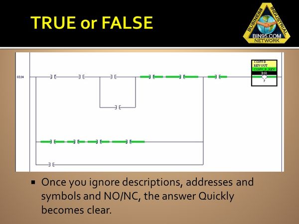
In this PLC troubleshooting example let say the conveyor is stuck in reverse. The first step is to go online with the PLC and search for real-world output to the conveyor reverse motor. In this troubleshooting example pictured above, you see there are 3 different branches of which anyone could cause the motor to be on all the time. With all other distractions out of your mind, now it is clear that the second branch of the rung (circuit) has all its conditions true (highlighted green) and is the cause for the motor being on.
In the real world, the conveyor is running all the time, and this is the undesired effect. So now it’s time to analyze the second branch of the rung to determine what condition is currently true, which should not be true at this moment in time.

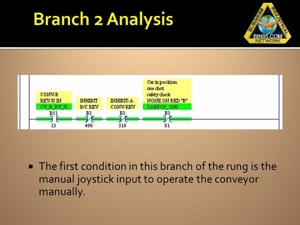
Now that we narrowed down the problem to one branch of the rung/circuit, we can determine which of the four conditions on that branch shown above is the culprit. For this small part, we read the descriptions to determine which condition made, should not be made(true) at this moment in time. By the description of the first condition, we can logically deduct that the manual joystick is stuck on the conveyor control because no one is operating it. Yet the condition is TRUE in the rung and causing the conveyor to continuously run.
Notice that at this point in the troubleshooting, we identified the real-world input causing our problem and still did not have to think, “Is the rung instruction (element) Normally Open, or Normally closed?” We still have not had to worry about what the address of the instruction (element) is.
It is not until we advance to the repair part of the session that we now need to determine, "Is the joystick supposed to be wired normally closed or normally open"? (It may have been recently replaced and wired wrong) or "Is it just mechanically stuck"? Actually, to check the switch out we still do not need to figure out which way it should be wired. We could just simply activate the switch and see if the instruction on our laptop changes from true to false. (If it does, the switch is wired wrong, if it doesn’t change states, the switch is stuck)
This method of using the PLC to isolate what is the failed component typically takes about 4-8 minutes regardless of equipment complexity, if the technician had proper PLC training. In contrast, troubleshooting the same problem using a VOM instead of PLC, typically takes from 30 minutes to several hours depending on complicity.
CNC Troubleshooting Example
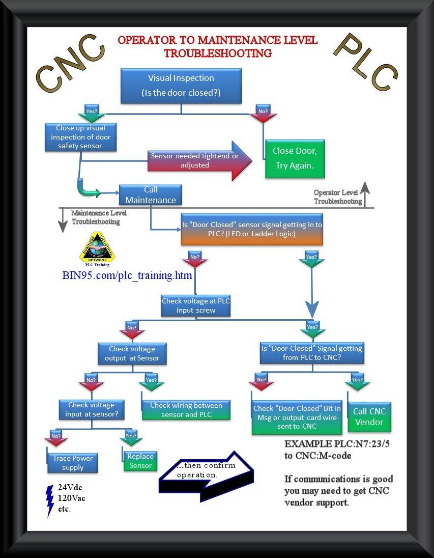
This CNC PLC troubleshooting flowchart example is based on the scenario the CNC machine won't start due to the safety door not closed indicator on the CNC operator control panel. From machine operator level CNC troubleshooting to maintenance technician PLC troubleshooting, this CNC - PLC troubleshooting flowchart will help to understand the process.

CNC Operator:
Some CNC operators perform initial maintenance technician troubleshooting steps above, but the majority pretty much conform to the above flowchart. The CNC operator is typically limited to the limited control access a CNC controller provides in the CNC operator control panel, whereas maintenance has access to the full control, performing PLC troubleshooting.
- Visual Inspection (Is the CNC door closed?)
- No?
- Close Door, Try Again.
- Yes?
- Close up visual inspection of CNC door safety sensor.
- Did sensor need tightened or adjusted?
- Yes?
- Close Door, Try Again.
- No?
- Call Maintenance
- Yes?
- No?
Maintenance Technician:
The maintenance technician job description (or field service technician) is to troubleshoot at a more complex level to determine faults with wiring, devices, and communication issues between even more complex control devices (CNC PLC). The maintenance technician who has had proper PLC training, uses the PLC (Programmable Logic Controller) to make troubleshooting about 80% quicker and easier, and is referred to as "PLC Troubleshooting". Within the basics steps shown in the above PLC troubleshooting flowchart, there are additional steps, but we simplified the flowchart for illustration purposes.
- Is the "Door Closed" sensor signal getting into PLC? (PLC LED or Ladder Logic)
- Yes?
- [2] Is the "Door Closed" signal getting to CNC from PLC?
- No?
- Check "Door Closed" bit in Message or Output card wire sent from PLC to CNC. If "No", trace back in the PLC program and/or wiring accordingly.
- Yes?
- Seek CNC vendor support. There may be an additional input or M-code required for the CNC operator control panel to indicate "Door Closed"
- No?
- Check voltage at PLC input screw.
- Yes?
- Is the "Door Closed" Signal getting from PLC to CNC?
- No?
- Check the "Door Closed" Bit in Message or output card wire sent to CNC
- Yes?
- Call the CNC vendor
- No?
- Check voltage at the CNC door sensor output
- Yes?
- Check wiring between the CNC door sensor and the PLC
- No?
- Check the voltage at the input to the CNC door sensor
- No?
- Check the power source to the CNC door sensor
- Yes?
- Replace the CNC door sensor
- Yes?
Most "CNC Maintenance" and even "CNC Troubleshooting" courses or sections in CNC manuals actually do not even include PLC Troubleshooting. But as you can see from the CNC PLC troubleshooting flowchart example above, the PLC is an integral part of CNC control. The CNC controller works with the PLC controller to complete the full process.
If you would like to reference this guide offline, and/or print copies for your maintenance, operators, or students in your facility, you can purchase a PDF version of this guide below.
<< Back to chapter 4, Maintenance Management and Asset Management.

