Mechanical Maintenance Technician Guide
- 1. Engineering Principles for Maintainers and Operators.
- 1.1. Work within the design limits
- 1.2. Force transmission
- 1.3. Stress in materials
- 1.4. Clearance, fits and tolerances
- 1.5. Bending stress
- 1.6. Torque stress and combined loads
- 1.7. Metal fatigue failure
- 1.8. Lubrication
- 1.9. Vibration
- 1.10. Chemical and material compatibility
- 1.11. Corrosion
- 1.12. Fluid flow
- 1.13. Cavitation
- 1.14. Welding metals
- 1.15. Welding plastics
- 1.16. Heat transfer
- 1.17. Bearing isolation and protection
- 1.18. Electric motors
- 1.19. Process control and monitoring
- 2. Equipment Maintenance Best Practice.
- 2.1 Creative disassembly
- 2.2 Bolting and gaskets in flanged connections
- 2.3 Threaded connections
- 2.4 Chain and sprocket drives
- 2.5 V-belt and pulley drives
- 2.6 Mechanical seals
- 2.7 Soft-foot distortion
- 2.8 Shaft alignment
- 2.9 Pneumatic valve actuators
- 2.10 Process control valves
- 2.11 Isolation valves
- 2.12 Roller bearings
- 2.13 Oil cleanliness
- 2.14 O-ring seals
- 2.15 Gear box drives
- 2.16 Gland packing
- 2.17 Vibration control
- 2.18 Non-destructive testing of welds
- 3. Types of Maintenance Philosophies.
- 4. Maintenance Management and Asset Management.
- 5. Fault Finding and Troubleshooting Check Lists
... A continuation of the Free Online Industrial Maintenance Technician Guide
Copyright © 2003 - 2026 Business Industrial Network
All rights reserved. No part of this publication may be reproduced, stored in a retrieval system or transmitted in any form or by any means, electronic, mechanical, photocopy, recording or otherwise, without prior permission of the copyright holder.Because the authors, publisher, and resellers do not know the context in which the information presented in the book is to be used they accept no responsibility for the consequences of using the information contained or implied in any articles.
This a continuation of the Equipment Maintenance Best Practices section of the guide for the industrial mechanical technician studying maintenance technology. If you would like to reference this guide offline, and/or print copies for your maintenance technician, operators, or students in your facility, you can purchase a PDF version of this guide at the bottom of this page.

2.9 Pneumatic valve actuators
Pneumatic (air operated) actuators are the preferred device used to automatically open and close quarter-turn valves. They consist of a ram moved by air pressure within a cylinder. Long-lived actuator operation depends on the air quality, the compatibility of materials of construction, the simplicity of the design and the quality of the installation.
A quarter-turn valve goes from fully open to fully close in 90o of rotation. Examples are butterfly, plug or ball valves. Figure 1 shows an actuated butterfly valve in a pipeline operated by a solenoid valve.

To open the valve automatically from a remote signal a mechanically operated actuator is mounted on top of the valve. The pneumatic actuator connects the valve stem to a piston inside the actuator. A solenoid valve directs air to one side of the piston or the other and the stem rotates.
The solenoid valve contains an electric coil, a shuttle plunger, and a spring. The plunger covers openings within the solenoid body. When power is applied to the coil it becomes magnetized and pulls the shuttle into place. When the power is turned off the spring pushes the shuttle back. The electric power is turned on and off by a signal from the process computer. When the solenoid operates, compressed air flows through the open ports and onto one side of the actuator. The piston moves and the valve stem rotates.
The actuator can contain a spring that pushes the piston back into place on release of the air pressure. Actuators that are closed by a spring are called fail-close actuators. If air pressure is lost the valve will be closed by the spring and stop the process flow through the pipe. There are fail-open actuators where a spring keeps the valve open, and air closes the valve. Double acting actuators need air to both open and close the valve.
When a mechanical engineer is selecting pneumatic actuators they make sure the actuator can produce a greater torque than that needed by the valve. Butterfly valves used as outlet valves on silos of powdered product can bind when the product causes the torque between the disk and seat to increase above the capacity of the actuator. Air lines to the solenoid and the actuator should be the same diameter, and even one diameter larger, than the port connection. This permits the air to quickly flow to the piston chamber for rapid response. It also gives the piston a sudden surge to help break any seating torque.
Instrument quality air is best for long-lived reliable operation of air operated actuators. In particular, moisture must be removed so it does not condense in solenoids and actuators, something mechanical maintenance technicians are well familiar with. Trapped moisture causes corrosion inside the actuator and solenoid bodies and can hydraulically lock the piston at part-stroke and stop the valve from turning.
Ensure the pressure dew point (the temperature that moisture in the air condenses at system pressure) of the compressed air is well below the coldest distribution system temperature.
2.10 Process control valves
Control valves regulate the flow of a liquid or gas by opening or closing internal passages. They form part of a control loop used to control a process. The control valves respond to instructions from the controller and adjusts the internal openings accordingly.
Purpose of control valves
A control valve varies the rate of flow passing through itself. The valve stem moves, altering the size of the passage and this increase decreases or holds steady the flow. The control valve opening is altered whenever the process parameter being controlled does not equal the value it is meant to be (the set point).
Operation of a control valve
A control valve consists of three key components - the valve, the actuator, and the controller. The valve can be one of two basic types. A plug and seat design, in which a plug is closed against a seat or a quarter turn valve in which a disc, ball or cone is turned against a seat. The drawings below show the two types of control valve.


The actuator is used to move the valve stem. They are usually air (pneumatically) or electrically driven. The controller calculates the size of the change to the valve internal passage to bring the flow to the desired rate.
The rate of flow through the valve depends on the pressure difference between the inlet and outlet. To slow the flow the valve is closed which causes more back-pressure and a greater difference between the inlet and outlet pressures. To increase the flow the valve is opened which reduces the backpressure and the pressure difference across the valve.
The portion of the valve that regulates the flow is known as the valve trim. It consists of a fixed-in-place seat and the movable plug, disc, ball, or cone. The trim can be selected to create a variety of passage shapes that control the flow.
Control valve tuning
The controller tuning dictates the way the valve responds to the changing process parameter. Tuning of a control valve sets the speed and intensity of the valve response when the need for a correction is detected.
The controller contains internal logic that produces an output to the actuator to move the stem a predetermined amount. This logic looks at:
a) the size of the discrepancy between the set point and the current value of the controlled parameter (Proportional)
b) the length of time the discrepancy has been present (Integral)
c) the speed at which the discrepancy has been changing (Derivative) and determines how fast and how far to move the stem.
Once the position of the trim is altered the controller waits for the next sample signal from the sensing element to check the difference remaining to the set point. The valve stem is moved, and the flow altered until the difference between the set point and the actual value of the controlled parameter is within tolerance. An example of tuning a control valve can be likened to a person under a shower adjusting the taps to get the water temperature right. The sketch below shows the logic involved in controlling the water temperature.
If the hot water is first put on, the control valve becomes the cold-water tap. Your body senses the temperature of the water. If the water is too hot you open the cold-water tap. You wait a while (the time lag) to sense the effect of increasing the cold-water flow. The cold water is adjusted until the temperature from the combined flows is just right. Once the temperature is right the valves are left alone and the temperature is stable. If a change occurs, such as someone doing the laundry with cold water, a drop-in cold-water flow to the shower occurs and the water temperature gets hotter. You again sense the changing temperature and make the necessary adjustments. In response the cold-water tap is opened further or the hot water tap is closed.
This whole process involved sensing the temperature and moving valve positions until the parameter under control (temperature) stabilized. A control valve works the same way.
Problems with control valves
- Control valves may not properly regulate the parameter they are controlling. If the process cannot be controlled product quality issues arise.
- Control valves can be sized too large. An overly large control valve is wasted money and is insensitive when fine adjustments are needed. Usually control valves are one- or two-line sizes smaller than the pipe.
- A control valve can have excessive lag (react too late) because the sensor is located too far away.
- The actuator air supply may be low or leaks away and so produces insufficient force to move the stem.
- The control valve stem can become sticky if the packing is tight or product leakage causes binding of the stem.
Control valve sealing classification
Metal seated control valves are classified into classes reflecting the quality of sealing. The higher the valve class, the smaller the leakage rate allowed when closed; the finer the manufacturing requirements and the more expensive to buy. Table 1 shows the various control valve sealing classifications.
CLASS
TEST
TEST PROCEDURE
ALLOWED LEAKAGE
FLUID NOTES
I
-
-
-
No test performed
II
Water or air
385 – 490 kPa
0.05% of full rated capacity
Pres & flow measured to +/- 10%
III
Water or air
385 – 490 kPa
0.1% of full rated capacity
Pres & flow measured to +/- 10%
IV
Water or air
385 – 490 kPa
0.01% if full rated capacity
Pres & flow measured to +/- 10%
V
Water
Max differential pressure
0.0005 ml per minute per inch diameter per 7kPa
Pres & flow measured to +/- 10%
VI
Air or Nitrogen
350kPa
Varies with diameter. See ANSI B16.104
Eg 6 or less bubbles for 3” diam valve
Table 1: Sealing classes for control valves.
2.11 Isolation valves
The purpose of a valve is for isolation or regulation. Isolation valves seal the fluid off on one side of the valve. Regulating valves meter, the flow through the body. Valve used for isolation duties must provide secure, tight shut-off.
The construction of valves
The essence of valve operation is closing or opening a gap by moving one surface against another. This occurs within the valve body. In the case of manual and actuated valves, a stem sticks out of the body and must be sealed to prevent leakage. Figure 1 shows a variety of valve and seat sealing arrangements. Consideration must be given to the nature of the process chemical, the quality of sealing and the impact of outside environmental occurrences.

Acceptable leakage rates from valves
Valves are constructed to manufacturing standards that specify performance requirements for the materials used in the valve. The completely assembled valve is also required to pass leakage tests. Two widely used leakage standards are API 598 (American Petroleum Institute) and BS 6755 (British Standard). Both standards accept some leakage from certain styles of valve. Table 1 shows what is acceptable in API 598.
Resilient valves are those with one or both sealing surfaces made of plastic or rubber. When a resilient valve is tested with liquid no leakage is allowed during the test period. If tested with a gas one bubble is allowed during the test period.
Size Range Inches
Resilient Soft-seated Valves
Metal Seated Valves Except Check
Liquid
Gas
Metal Seated Check Valves
Liquid
Gas
≤ 2
0
0
0
0.18 in3 (3 cm3) per minute per inch nominal diameter 1 cm3 = 16 drops water
1.5 std ft3 (0.042m3) of gas per hr per inch nominal diameter
2 ½ - 6
0
12
24
8 - 12
0
20
40
≥ 14
0
20
40
Table 1: API598 leakage rates.
The test pressure used for most valves is 110% of the maximum allowable pressure for which the valve is designed at 38oC (100oF). But for butterfly valves it is 110% of the design differential pressure. When the maintenance technician is ordering butterfly valves, they must specify the maximum in-service pressure. The differential pressure rating is the ability to hold pressure from one side of the valve to the other. The allowable pressure depends on the materials from which the valve is made, and the stresses allowed in the materials.
The test pressure is held on the valve for a set period of time defined in the applicable standard. Table 2 is from API 598 for a high-pressure closure test.
Minimum test duration in seconds for closure test.
Valve size (inches)
Check valve
All other valves
≤ 2
60
15
2 ½ - 6
60
60
6 - 12
60
120
≥ 14
120
120
Table 2: API 598 pressure holding times.
More demanding standards are available. An example is API 6D, which allows no visible leakage during the test period. However, manufacturers will find it difficult and costly to achieve such a standard for metal to metal seat valves. Valve manufacturer’s catalogues specify which standards they meet.
Fire rated valves
Fire testing exposes valves in the closed position, filled with water under pressure, to flames producing a temperature near the valve of 760oC – 980oC for a 30-minute period to establish a leakage through the valve to atmosphere. After cooling the valve is pressurized with water to assess the pressure containing capacity of the valve body and seats. If the maintenance technician requires fire rated valves, they ask for test documentation.
Considerations when selecting valves
What the tables above do not say is that metal seated valves larger than 2-inch may leak from day one and get progressively worse with use. For many services that may not be a problem. However, for corrosive, hazardous, and toxic gases and liquids it is important to know that most metal seated valves leak minutely. Picking the right valve is critical for safe operation. If bubble tight closure is truly needed then resilient, soft-seat valves are.
The tests do not consider effects such as distortion from ‘water’ hammer, high seal face open – close cycles, high temperatures and temperature differentials causing thermal expansion, chemical degradation like corrosion of sealing faces and ‘wire draw’ across slightly open valves. One option, for more reliable isolation using all metal valves, is to use a double block and bleed configuration. Two valves are installed slightly apart, and a third valve is used to drain the pipe between them.
The other location that can leak is at the valve stem. Check that the packing or sealing o-ring(s) is suitable for the service. An example is where the manufacturer installs packing for hydrocarbons, but the maintenance technician requires the valve for process chemicals. In this case they change the packing to the right type for the process.
Beware of valve stems that are exposed to the process. If a valve stem extends into the process fluid when closed, and rises when open, there will be a thin smear of chemical clinging to the stem as it wipes past the seal. The raised stem is now exposed to environmental conditions. The process chemical may dilute with moisture and attack the stem, or it may dry on the stem and cut the seal when next lowered.
Other operating considerations include:
- Whether the lines are to be pigged (use full bore valves)
- Liquid thermal expansion causing pressure build-up between closed valves (install pressure bypass valving)
- Position indicators to show close- open position
- Back seating to prevent stem leakage when valve is open
- Product build-up on seat faces (stroke the valve regularly)
- Pressure loss minimization (use full bore valves and straight through designs).

Want to learn more about pneumatics and hydraulics? See our interactive certificate course "The Pneumatic, Hydraulic Fluid Power Training Course". This course is Great for a hydraulic engineering preparation course or refresher and for mechanical maintenance technicians. Interactive hydraulic simulations you won't experience in NFPA? - Hydraulics Online Training courses.
2.11 Roller bearings
A shaft must always be allowed to expand along its length. This is achieved by installing a fixed bearing (the locating bearing) at one point and mounting the other bearings so they can move axially. Select bearings for the ‘floating’ positions that allow the inner raceway to slide past the rolling element (e.g., cylindrical roller bearings) or fix the bearing on the shaft but leave the outer race loose in the housing.
Preload is the purposeful application of a force on the bearing to ensure the rollers a properly contacting the raceways. Preload is also provided to counter thermal growth and insure that at operating temperature the correct clearances are kept in the bearing. Where the shaft growth is more than the bearing housing growth any preload will be increased by the shaft expansion. In such cases it is necessary to leave clearance at assembly so that at running temperature the expansions achieve the correct clearances.
Axial preload is used to prevent the balls sliding on the raceway. As the shaft rotates the rolling balls also move around the shaft but at a different speed. When the balls move into the loading zone they must start to roll over the raceway and take their share of the load. If instead there is too much clearance between ball and raceway the ball can skid. This can cause the lubricant film between ball and raceway to separate and allow contact. Axial preload makes the rolling elements and raceway come into contact on purpose, so no clearance exists between them when they are still. There is very slight deformation of the raceway and the balls. The lubricant film builds-up between the race and the ball when they are moving.
Set clearance and preload to that recommended by the manufacturer for the bearing size and running temperature. To maintain correct clearance when in operation, and to create a load zone, bearings set back-to-back or face-to-face must be subject to additional radial loads above that of the preload. This can be done by increasing the drive belt tension or by ensuring the self-weight of the shaft and components are more than the preload force.
Misalignment can arise from the operating load causing bending, it can also arise when bearing housings are not machined at a single setting and from the self-load of a shaft and attached components if bearings are mounted far apart.
Ensuring bearings are well lubricated is always a critical requirement. If the bearing is oil lubricated in an oil bath insure the oil level always contacts the lowest roller as it comes around so the roller can splash lubricate its fellow rollers and the raceways. Do not over fill the oil bath because when the rollers come around, they will have to force their way through the oil and this causes additional heat. The oil level should be no higher than midway up the most bottom roller as it comes around the raceways.
To ensure the rolling elements will actually rotate as they come into the loading zone of the bearing there must be a sufficient minimum load. If the self-load is insufficient then an extra radial load will need to be applied. This can be by increasing belt or chain tension or purposely increasing the torque on the shaft.
Angular contact bearings
Angular contact bearings are used on shafts that encounter axial forces or combined loads (both axial and radial forces). Examples are centrifugal and helical rotor pump shafts and helical and worm gear shafts in gearboxes. Their design only permits axial forces in one direction. For alternating axial loads they must be installed as a bearing set to accommodate the forces from both directions. When set back-to-back, and less so when set face to face, they act to stiffen the shaft and handle larger bending moments such as overhung components or high midpoint shaft loading.
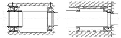
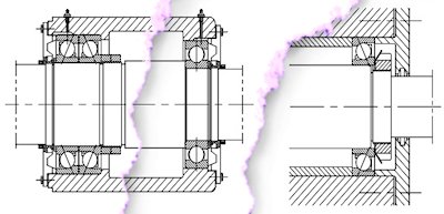
Figure 1 Angular Contact Bearings Arrangements
Hover over picture above to zoom in.
Figure 1 shows angular contact bearings in a back-to-back arrangement (left) and in an opposing arrangement. When in direct contact (left of Figure 1) they are good bearings to use as locating bearings on a shaft because they can take combined loads. They are not suitable for the non-locating bearing because the ‘floating’ bearing must allow shaft axial movement due to thermal growth.
The biggest limitation of angular contact bearings is their inability to accommodated shaft misalignment. It is critical that parts be machined true to the axis, that tolerances and alignments be checked during installation and confirmed suitable, that components be made of materials and have cross-sections which resist bending. Misalignment causes forces that produce greater ball bearing loads and retaining cage stresses. The higher stresses reduce bearing life.
The correct internal clearance and preload in single row angular contact bearings can only be achieved after mounting them on the shaft and adjusting them against a second bearing providing axial location in the opposite direction (right of Figure 1). When used back-to-back or face-to-face the clearance cannot be adjusted. It must be provided by proper choice of bearings with appropriate clearances and use of fits for the shaft and the housing that on assembly gives the necessary clearance and preload.
Spherical roller bearings
These bearings are popular because they can take very heavy loads and are self-aligning. Their design allows them to take combined loads in both the radial and axial direction acting together. Each roller is loosely retained in place within a cage that goes full circle between the raceways. Figure 1 shows a simplified drawing of a spherical roller bearing (SRB) on a shaft under deflection.

The shape of the rolling elements provides its name. The contact surface is the curved portion of a sphere, and the curvature allows the carrying of axial loads. The axial load carrying capacity is less than that of an angular contact bearing but unlike angular contact bearings (unless paired back-to-back or face-to-face), SRB’s can take axial loads in both directions.
SRB’s permit misalignment between the inner and outer races. The bearing takes up the misalignment by allowing the rollers to pivot in the raceways. Because the bearing races can rock independently SRB’s cannot resist a moment load (a load that is acting to tilt or snap the shaft). Double row angular contact or taper roller bearing can be used in such situations. They are forgiving of slight alignment errors and are a good selection for equipment experiencing vibration.
For vibrating machinery (e.g., vibrating screens) the bearings are provided with an extra guide ring that runs between the rollers along their inside ends and keeps them square to the race. This center guide increases the bearings working life by reducing roller chattering on the raceways.
The SRB’s come with factory set internal clearances and no preload is required. Because the clearances are factory set it is important to select the right bearing clearance for the application, especially where the bearing runs hot. Since SRB’s cannot be preloaded, the load must come from the shaft and the attached components. The bearing supplier can perform calculations to confirm the in-service bearing load.
SRB’s can be lubricated by grease or by oil. In difficult service they will need extra attention to ensure the lubrication is actually getting into the running area. To accommodate this, the larger sized bearings from the quality bearing manufacturers have a grease groove machined into the outside of the outer race with several grease holes through the race into the running area. Ensure the bearing housing grease nipples are located directly over the grease groove.
2.13 Oil Cleanliness
When oil in gearboxes become contaminated there is a rapid loss of bearing operating life. It is critical that metal particles, dirt, sand, oxidization products, etc be removed from the oil before they gouge and tear-up the finely tolerance machine parts. Oil replacement, contamination prevention and oil filtration are common practices religiously adopted by the best in the equipment reliability management business.
Wear in moving equipment such as gearboxes, pump bearings and hydraulic rams is a function not only of how much work the item does but how we treat the lubricant at commissioning and during operation.
Looking firstly at the commissioning phase, a survey quoted in an SKF publication of drummed fresh gearbox oil found surprising levels of particulate contaminants. The action to cover this problem (especially at remote mine sites) is to filter your oil prior to charging a piece of equipment. This leads to the question of what sort of filter? Some filters are wire mesh or paper based, others are made from synthetic fibers locked in position with epoxy resin. Another aspect of the quality of the filter is the fiber size with respect to the gap size. Clearly a filter with fine fibers for a particular pore size will have more pores and will last longer. So cheapest may not be best. When filters are tested, they measure the particles going in verse those coming out. The ratio is known as ‘β’ and the subscript represents the particle size it was tested at. Filters having a β6 rating of 75 or better are suitable for filtering gearbox oil. This code means that 74/75 of the particles of 6 microns or bigger is removed.
The recommended 6 microns comes from the concept that in operation, the oil film thickness or the “dynamic clearance” of different types of machine components varies. In journal bearings it is 0.5 to 100 microns and in roller bearings 0.1 – 3 microns. A study by Dr McPherson showed that as the filter rating particle size dropped from 40 to 3 microns, the roller bearing fatigue life increased exponentially. In plain English that means the more care the maintenance technician takes of oil cleanliness, the longer the equipment will last - and it is not just a little bit of extra benefit. The technician who pays the most attention gets the elite performance.
So, what do the elite performers do? Apart from taking care on commissioning, they monitor the oil and pay attention during the commissioning phase. A study by SKF on gearboxes showed that hard particles went from 100 on startup to about 8000 after 5 hours, to 10,000 per ml after 38 hours. So, change or filter your oil in the early stages after commissioning. Then look after it during operation, because when metallic particles, sand, dirt, etc bridge component clearances, the ‘little blighters’ are going around grinding and grooving their way through the circuit and the machine parts. The more of them that there are - the more damage is being done. Hey, it’s obvious isn’t it! But do we act accordingly?
A team of people at Weyerhaeuser (an American paper mill) systematically set about dissecting problems, introduced precision lubrication systems, contamination control and monitored their efforts by oil and vibration analysis. The result: An average of 25 bearing failures annually for 1980 – 1989 then after the program less than 5 for 1990 –1999. The downtime cost means real money lost in that section of the plant.
Typical dynamic (in motion) clearance values are:
Gear type oil pump:
Tooth to side plate: 0.5-5 micron
Teeth tip to case 0.5-5 micron
Vane type oil pump:
On sides 5-13 micron
On vane tips 0.5 – 1 micron
Servo valve:
1-4 micron
Roller bearings:
0.1 – 3 micron
From these figures, it can easily be seen that very small particles are going to make a difference to the life and free operation of equipment using oil.
And another bad thing is water ingress! The table below shows how bearing life is affected terribly by water ingress:
Water % in oil
% Bearing life remaining
0.01
100
0.05
38
0.15
20
It is common in industry to use hoses to wash down. So where does this water go? It goes into your gearboxes and pumps.
Often bearing failure is caused by a breakdown of the oil seal followed by all the ongoing ramifications (issues) of shaft seal failure allowing dirt and water ingress. Protect seals from the combination of wash down water, dust, and sun. By keeping out the contaminants there should be a marked rise in trouble-free operating bearing life.
2.14 O-ring seals
Properly designed o-ring grooves and properly installed o-rings stop the passage of pressurized liquids or gasses. O-rings are made of elastomeric materials such as rubbers and plastics. Flexibility while being deformed under pressure is their greatest sealing advantage. They deform under pressure and then return back to their original shape once the pressure is removed.
O-Ring Design and Materials
O-rings are available in various types of rubber. The choice of rubber depends on the chemical compatibility with the contacting fluid and the degree of harness needed to provide long-lived wear properties. They must be able to deform during assembly and in operation and accept the movement of mirror-finish shafts while deformed by pressure. Usually, they are shaped like a rubber elastic band of round cross section, but they can have rectangular, trapezoid and even ‘+’ shapes depending on the application. The material, internal diameter (ID) and cross section diameter specify o-rings of round cross section.
O-ring Groove
An o-ring is fitted inside an o-ring groove to locate and shape them ready for the application of pressure. The dimensions of the groove can be found in design reference books for the size of o-ring concerned. A most important requirement for the groove is that its depth produces a diametral squeeze on the o-ring to compress it and develop flat sealing surfaces against the top and bottom of the groove. There should be 40 to 45% of the original o-ring cross sectional area as a sealing surface at ZERO pressure. The groove needs to be wide enough to accept the material that is squeezed sideways and allow for slight o-ring movement when the pressure is applied. If the operating temperature is elevated the groove must also be wide enough to permit thermal growth of the elastomeric material.
Figure 1 shows a properly compressed o-ring both with and without the application of pressure. Note the flat sealing surface top and bottom caused by the squeeze of the groove components. Pressure pushes the o-ring up against the wall of the groove and it is deformed to produce three sealing faces. The more the pressure is applied the better the seal developed.

Limitations of Use
The rubber and plastic compounds from which o-rings are made have limitations. Rubbers and plastic have limits on their operating temperature range. Also, the elastomeric compound of the o-ring may not be compatible with certain chemicals. These issues must be checked. The properties of the elastomeric can be found from the o-ring supplier.
Installing O-rings
O-rings are soft and easily damaged. Once nicked, cut, or abraded they will never seal properly and must be replaced. Remove o-rings with a rounded wooden or plastic spatula. Never use sharp steel, metal wire or screw drivers to remove them as these quickly and easily cut into the elastomeric (and your hand) and damage it.
The O-ring and groove must be free of dirt and debris when installed. Any foreign material squeezed into the groove will lead to leakage. Clean o-rings with a lint free cloth by holding the cloth in hand and gently pulling the o-ring through around its entire loop several times. Inspect it under good light to confirm it is in good condition. Clean the recessed groove out with a lint free cloth or Q-tips (cotton tips). Remove all old lubricant, oil, and dirt.
To mount the o-ring into the groove may require that it be stretched over part of the component. Warm the o-ring to soften it. Any edges must be chamfered and deburred. Depending on the o-ring material a lubricant can be lightly applied to the o-ring to help it slide. Check with the o-ring supplier as to the appropriate lubricant for the o-ring.
2.15 Gear box drives
A gearbox is used to control the operating speed of industrial equipment. Mechanical maintenance technicians know the proper selection, care and maintenance of gearboxes is critical. Failure of the gearbox causes the equipment and associated plant to stop. Keywords: service duty, drive, breather, lubricant, oil analysis.
Gear box selection
CATEGORY
CONSIDERATIONS ...
Load type
- Steady, consistent.
- Intermittent, on-off, fluctuating.
- Impact, hammering, surging.
Environment
- Temperature of location.
- Cooling and heat dissipation.
- Dustiness.
- Humidity, dampness.
Forces
- How are the forces created?
- Where are the forces located?
- Where are the forces transmitted?
Robustness
- Is the mounting sturdy?
- Will the shaft handle the torque?
- Is the casing solid and rigid?
- Is there sufficient excess service duty to handle unexpected loads?
Drive
- Direct coupled, chain, belt driven.
- Minimum bearing loads required.
- Orientation of gearbox in relation to forces generated.
Gear type
- Loads and forces applied to gears.
- Heat generated by the meshing.
- Lubrication type.
Maintenance
- Parts availability.
- Standardization across the site.
- Skill level of maintainers.
- Presence of procedures.
Operations
- Production demands.
- Operator care.
- Overload potential.
A gearbox is selected for the duty it must perform. It converts a high input speed to a lower output speed and so permits one driver element, such as an electric motor, to do numerous duties. Each selection must take consideration of the following points.
For example, in the selection of a gearbox to be direct coupled to an agitator for a stirred tank, consideration must be given to the distance the output shaft bearings are apart. Bearings positioned further apart cope better with the bending forces generated by the paddles located at the end of the agitator shaft.
The load type will affect the selection of the gear type. Steady, continuous loads can be accommodated by spur gears, but impact loads can break spur gear teeth. A more robust gear to use in impact load situations would be a helical gear. This gear shape offers more tooth cross-sectional area and because of the helix dissipates impact forces axially and tangentially.
Another style of gearing often seen on slow moving, high load applications is the worm and worm wheel. Planetary gearboxes are available where space is limited for standard design gearboxes.
Gearbox care
A well-selected gearbox will have a long service life. Long term maintenance by the mechanical maintenance technician will involve checking oil levels and for critical or expensive gearboxes checking oil quality. Oil quality ought to be tested at least every year for stationary plant and every sic months for mobile plant. More often if the loading or service duty is arduous. A simple site test for gearbox oil is to take a sample and look at the color, note the smell, look, and feel for presence of grit and feel the slipperiness compared to fresh oil. If maintenance technician is concerned, then they send a sample to a lubrication test lab.
An oil analysis includes tests for the oil’s lubricity, changes in the oil’s condition, condition of additives, solids particle counts for larger than 2-, 5- and 15-micron particles, moisture pick-up, dust/dirt contamination and the metals in the oil.
The choice of lubricant is critical. The oil must retain its properties at the operating temperature. The gearbox manufacturer is best able to advise the oil to use. Where the manufacturer cannot be contacted, one of the major oil companies can offer practical suggestions on the oil to use. Mixing of different oils in the same gearbox is poor practice. Unless the maintenance technician can tell the oil supplier with certainty what oil is already in the gearbox so a match can be specified, do not cross mix oils. Mineral and synthetic oils are not compatible. It is better to drain the old oil out, flush the gearbox through with the new oil, put in the new oil to the required level and run the gearbox for two to three hours and finally dump, flush, and refill the gearbox again.
Breathers are fitted to prevent shaft seals blowing out as the internal pressure rises when the gearbox is warming up to operating temperature. A breather allows moisture in the air and dirt from the surroundings to enter the gearbox. Locate and protect the breather to reduce the risk of contamination. Check with the gearbox manufacturer to see if a breather is needed and if not then do without it. Breathers in dusty locations require an air filter to clean dust particles 2 micron and smaller. Where they are exposed to hosing down, they must be protected from water ingress by shrouding or by locating the air intake at the end of a hose extended to outside the wash down region. Ensure the hose is well clamped at the gearbox and breather intake.
Unexpected high working loads can occur that will destroy gearboxes. For overload conditions shear pins can be installed in the drive train or motor overload protection can be fitted to the power supply. For those services where impact loading is normal such protection is mandatory. A belt or chain drive gearbox should be oriented so the forces in the drive pull the gearbox down onto its feet. Where the orientation of the gearbox causes the gearbox to be pulled off its feet there is a risk the feet will break from fatigue caused buy fluctuating loads. In this case additional clamping of the body to the support frame may be necessary.
Gearbox maintenance
When a gearbox is open cleanliness is critical. Dirt and dust entering bearings and gear teeth spaces will cause wear and rapid failure. If gears with chipped teeth are reused, chamfer the chipped edges to remove loose metal. Gearbox bearings may require pre-loading to a minimum bearing load to prevent excessive noise and wear. Pre-loading bearings ensure the rolling elements are properly bedded onto the races and prevent the rolling elements skipping and sliding around the tracks.
2.16 Gland packing
Compressed, stacked packing is used to seal the hole created by a shaft passing through a piece of equipment. The sketch below shows a typical packed shaft configuration.

Because compressed, stacked packing requires leakage to cool and lubricate, one would normally use packing on benign products. If used on environmentally unfriendly products or dangerous goods, the leakage must be collected and suitably treated to protect people and environment.
How compressed packing works
As packing is squeezed into place it fills the cavity in which it sits. The packing will seal against the side and bottom of the stuffing box and on the shaft surface. When the shaft turns, it rubs against the packing and is wiped clean. Except for slurries, 70% of wear normally takes place in the first two packing rings nearest the gland throat.
Considerations when using packing
Because packing rubs on the shaft, friction is generated, and wear occurs. The preferred methods of minimizing shaft friction are to:
- Use a very smooth surface finish.
- Use a hardened rubbing surface (protect the shaft with a hardened, replaceable sleeve if practicable).
- Use the slowest shaft speeds allowable.
- Ensure stuffing boxes are cylindrical; shafts are machined round and run true to within 0.08 mm (0.003”); the gland throat clearance prevents packing extruding through it (maximum of 3% of packing width).
- Install a lantern ring to flush away contaminants.
- Install a lantern ring to feed a cooling and lubricating fluid to the rubbing surface.
- Select packing which helps heat to be removed.
- Elect packing with friction minimizing properties.
- Select a braid structure suited to the process fluid and pressures - close twined for gasses and high pressures.
- For valves the packing cross section must be a snug fit in the stuffing box; for pumps packing cross section must have a slight (3%) clearance in the stuffing box.
Good installation practices
To minimize the extent of leakage from a packed gland do the following:

- Cut each ring with a slanted end join as shown below
- Install the packing with each ring join staggered 90 degrees from the previous
- Set each ring individually in place with a tamping tool, or split hollow cylinder, turning the shaft occasionally
- Push each ring hard up against the previous ring with no gaps. This ensures the force generated by tightening the gland follower is transmitted to all rings
- Lantern rings must line up with the flush port
- Continue fitting rings until the gland follower projects 25% to 30% of the stuffing box depth
- A lantern ring flush must be a clean source and at a pressure 100 kPa (15 psi) above stuffing box pressure (about two thirds the discharge pressure)
Commissioning shaft packing
Commissioning a packed gland is a slow process. Proper bedding-in of the packing on rotating applications will take two to three hours to achieve. Start with a generous leak and tighten the gland follower hand tight. Continue tightening evenly with a tool until the leakage flow levels off (even though the follower is being tightened). From then on make a half turn every fifteen minutes till the required leakage rate is achieved. Monitor heat build-up in the wall of the stuffing box by hand so it rises no higher than warm to the touch.
Packed glands on pumps, when properly seated and adjusted ought leak from five to twenty drops of product or flush liquid a minute.
2.17 Vibration control
Vibration in equipment is the result of unbalanced forces. Mostly a spring is used to isolate vibration movement, or a damper is used to absorb the movement. A full explanation of vibration control requires calculus and is beyond the scope of this article. The spring-mass-damper system sketch below is a simplified representation of a vibration control system. Spring force and damper pressure control the mass’ movement. The damper piston moves and so absorbs the vibration. Whereas the spring flexes and isolates the movement from its attachment.

The rate of vibration is called the frequency. It is measured in cycles per second and has the units Hertz. A four-pole electric motor rotates at about 1500 RPM?. This is 25 cycles per second or 25 Hertz. Vibration caused by an external applied force is known as a forced vibration because the mass oscillates at the frequency of the external force. An example is the shake produced by the moving pistons and crankshaft in a car engine.
Wild gyrations develop when the forced frequency nears the system natural frequency. Every system has a natural frequency and will shake to destruction if it is forced to move at that rate. This phenomenon is known as resonance. An example would be the shattered wineglass caused by an opera singer’s voice or vibrations in long, thin shafts that start and then stop as the shaft speed goes through its natural frequency speed.
Balancing rotors
Most importantly every moving mass must be balanced about its center of rotation. Rotating masses must be balanced to an acceptable standard. This is the first requirement for successful vibration control. Balancing is the process of attempting to improve the distribution of mass in a body so that it rotates in its bearings without unbalanced centrifugal forces. It can only be attained to a certain degree.
When a part is to be balanced it is necessary to specify the quality of balance required. Relevant standards have been set for various types of components. The list below is taken from BS 6861 and shows typical grades of balance for common components.
Balance Quality
Rotor Types – General Examples
G4000
Drive trains of slow marine diesel engines.
G1600
Drive trains of rigidly mounted large two-cycle engines.
G630
Drive trains of large four-cycle engines.
G250
Drive trains of fast, rigidly mounted diesel engines.
G100
Complete assembled engines of cars, trucks, and locomotives.
G40
Car wheels, wheel rims, wheel sets, drive shafts.
G16
Propeller shafts, individual car engine components, crushing machine parts.
G6.3
Fans, pump impellers, electric motors, general machinery parts.
G2.5
Gas and steam turbines, computer disks, machine tool drives.
G1
Grinding machine drives, tape recorder drives.
G0.4
Precision grinder spindles, gyroscopes.
Attaching or removing weight at relevant points on the rotor permits balance corrections. For example, specifically weighted tags can be welded to the rotor, or metal can be removed by drilling holes into the rotor at relevant positions.
To minimise the possibility of vibration problems, specify to the machine shop the degree of balance quality required of the part. To improve the accuracy of balancing send all the attached assemblies such as couplings, bolts, keys, and pulleys with the rotor so the effect of the components can be allowed for in the balance corrections.
Dampening vibrations
Materials such as rubber dampen shaking. The rubber flexes and absorbs the movement within itself. Figure 1 is of a simple rubber vibration damper. Because rubber cannot compress much to accommodate movement, rubber dampers are normally used for low amplitude, high frequency vibration where noise transference is a problem. Shock absorbers are used for large amplitude, low frequency situations where springs alone would produce bouncing. An example is in car suspensions.
The natural frequency can be moved away from the forcing frequency by changing the weight of the system. Making the frame of a vibrating machine heavier will lower the assembly’s natural frequency. Concrete added to the base frames of lightweight fans reduce vibration by lowering the natural frequency and moving it away from the forcing frequency produced by the rotating blades.
A vibrating mass can also be isolated from its surroundings by springs. The springs deflect under the shaking body. Installing isolation springs make the spring’s natural frequency the governing frequency for vibration transfer. Altering the spring stiffness allows us to select the desired amount of isolation.


Spring stiffness controls the amount of vibration transferred to the attachment. Too stiff will transmit vibration, while insufficient stiffness will cause bounce. The correct spring stiffness can be found using charts available from specialist vibration control companies. The isolation springs must not have a natural frequency near the forcing frequency of the isolated equipment. In such a case the system would start to resonate and jump about. Figure 2 shows an air compressor supported on springs. Stiffer springs are at the heavier end of the machine to both keep the machine level and to prevent resonance developing as the mass increases. The drawing also indicates that vibration is usually in more than one direction.
2.18 Non-destructive Testing of Welds
Welding processes and methods can introduce contaminants and metallurgical defects into the weld. If a weld is required to withstand severe loading conditions and stresses it is critical to ensure its quality meets minimum standards. Welds can be tested by destructive and non-destructive techniques. Most production is tested by use of non-destructive methods.
During cooling the weld quality can be compromised by inclusions such as slag, by human error from fatigue, by wrong set-up and technique, by equipment error due to breakdowns, by environmental effects such as low temperature and moisture, and by metallurgical phenomenon from incompatible metals or high cooling rates. Because welding is highly dependent on factors controlled by humans it maybe necessary to prove the quality of the work is suitably for the duty.
Visual Inspection
This method uses a qualified and trained observer watching the weld as the welder is working. The observer watches the weld pool and the cooling metal. They typically look for inclusions, undercutting (the weld height is below the parent metal height), depth of weld penetration and certainty of bonding to the parent metal.
Liquid or Dye Penetrant Inspection
As the name suggests a coloring agent is used to detect weld defects. This method will only find surface cracks and surface discontinuities. Only a clean metal surface is acceptable. The system normally comes in two spray cans – one is the penetrant, and the other is the developer. The penetrant is sprayed over the weld and capillary action draws it into any minute surface cracks. The penetrant on the surface is wiped off and the penetrant in the cracks remains wet. After a short dwell time the developer is sprayed over the weld. The developer acts to draw-out the penetrant dye from the cracks and so changes color. It behaves like blotting paper and magnifies the presence of the crack.
Magnetic Particle Inspection
This method uses changes in a magnetic field to detect surface and just-below surface discontinuities. When a magnetic field is interrupted by a defect, the field distorts around the defect. Powdered magnetic filings placed in the field can show this distortion. This method is only usable for Ferro-magnetic (iron based magnetic) metals.
Eddy Current Inspection
The principle of operation is the detection of changed electric current flow in a coil of electric wire. Alternating electric current flow through a coil creates a fluctuating magnetic field around the coil. If the magnetic field is brought close to conducting metal, eddy electrical currents develop in the metal. The eddy currents in turn set up a magnetic field in opposition to the coil’s primary field. Any fluctuations in the secondary magnetic field due to distortions also change the strength of the primary field, which in turn change the electrical current flow through the primary coil. The change in primary coil current flow is detected. The amount of the current change represents the effect of a discontinuity causing the distortion in the secondary field.
This method is used to detect weld defects deep into the metal. Depths of up to 25 mm are possible depending on the metal being tested and the speed of at which the alternating current changes (its frequency).
Ultrasonic Inspection
High frequency sound waves are sent into a metal using an emitting probe. If the waves encounter a discontinuity, they bounce off it and return to the probe where they are detected. The size and location of the discontinuity are displayed on a monitoring screen. The method cannot be used for surface and near surface faults. A dead-zone occurs just below the contact point of the probe. To insure proper acoustic connection between the probe and metal surface a liquid coupling agent, like grease, is used between the two.
Acoustic Emission Monitoring
Acoustic emissions are stress waves produced by sudden movement in stressed materials. When a material is placed under load it deforms ever so slightly. Internal movements produced by the deformation create sounds that travel through the structure. These sounds can be detected, and the source of the movement located. Once the source is found other NDT? techniques are used to quantify the movement and any presence of discontinuities.
Industrial Radiography
Radiographic inspection is based on the absorption of radiation by materials of different density. In the engineering industry X-rays or gamma rays are used. It is an expensive process but penetrates almost all materials to great depths.
The radiation source is put on one side of the weld being tested and the detecting ‘photographic’ film is placed on the other side of the weld. As radiation passes through the weld discontinuities act as density reducers allowing more radiation through them. The high level of radiation shows up as a darker color on the film.
If you would like to reference this guide offline, and/or print copies for your mechanical maintenance technicians, operators, or students in your facility, you can purchase a PDF version of this guide below.
On to chapter 3, Types of Maintenance, Philosophies and Methods ...
<< Back to chapter 1, Engineering Principles for Maintainers and Operators