Equipment Maintenance Best Practice
2. Equipment Maintenance Best Practice.
2.1. Creative disassembly.
This topic is the work of – Peter Brown Industrial Training Associates www.itatraining.com.au.
It would be rare for a machine to fail and not give some material or historical evidence of why it has failed. This material evidence must be looked at and some experiential opinion will be offered for the cause. Often the answers are already there. This process of Creative Disassembly is an important element of gathering the data that identifies the cause of premature failure.
All of us are problem solvers and, although we may be reluctant to see it as such, we are root cause analysts. At the end of the day we are all about preventing a repetition of the problem.
The collecting of information for analysis does not start with the stripping of the machine; it begins once the need for repair is identified and advances along two fronts, the historical and the operational or running characteristics. Further evidence is collected once the machine is stopped and before stripping.
Creative Disassembly
A machine is overhauled or repaired because it is no longer serviceable, it cannot perform the duties for which it is intended. To be confident that when the machine is returned to service it will do so reliably, it is necessary to identify the causes for the failure. All the evidence that is needed to achieve this will be present – the challenge is to obtain it and analyze it.
Where there is pressure for a machine to be returned to service with minimal delay there may not be adequate opportunity for this process. The options in such a circumstance may be:
- For maintenance to negotiate with production for the time needed, bearing in mind the repair may have many of the same problems returned with it and there is a high probability of further premature failures.
- To accept a temporary repair subject to a scheduled proper repair. When stripped for the second repair the machine is likely to have some particularly useful evidence available, especially if not run to destruction.
- To apply additional resources aimed at gathering the evidence and analyzing it as quickly as possible parallel to the repair process. It is possible to address many of the causes in this way. Others may be recorded for later correction.
In determining what to look for in Creative Disassembly keep in mind the nature of failures the machine is most likely to have suffered. For most industrial machines, the pattern of problem distribution is much as shown in the neighboring pie chart.
Major Causes of Machinery Problems
The three phases of collecting evidence are ...
- Prior to shutdown
- Shutdown, but prior to strip down
- Strip down
Pre-Shut Down
This is the time to gather historical and background data from CMMS?, operators and those who have worked on the machine previously. There is certain data that can only be obtained whilst the machine is still in service - Vibration and Bearing characteristics, thermographic and oil wear debris data for diagnostic purposes. Operating conditions need to be correlated with this. This can have a considerable bearing upon identifying the defect processes that are present.
There may be an opportunity to change some process variables which may give further insights to what is taking place.
Checks for running soft foot. Each hold down bolt is eased in turn and the change in vibration observed. Note that running soft foot is different to static soft foot; it occurs because of the thermal condition and /or the dynamic forces present.
Identify the presence of resonance in the machine, its base and supporting structure, and the pipe work or other attachments.
At Shutdown, but before Strip Down.
Before strip down begins there is valuable information that can be obtained;
- Where thermal growth may be an important factor for alignment considerations obtain a set of hot alignment readings. These are important not only for possible implication in Root Cause Analysis but for ensuring the data is used for future alignments in the cold condition.
- Look for witness marks such as cracked paint or shaft marks to indicate where there may have been relative movement taking place during operation.
- Deposited material indicating belt wear or coupling wear.
- Check for static soft foot.
- Sample lubricants prior to removal
Strip Down
- Look for witness marks, evidence of fretting etc.
- Disassemble in clean and well-lit areas.
- Photograph damage if applicable.
- Avoid damaging during removal.
- Mark the relative locations of bearings in housings, top and side, inboard and outboard.
- Inspection of bearings - when removed, prior to cutting.
- cut the cage/retainer rather than springing it.
- cut outer race from top centre to bottom centre.
- re-inspect prior to cleaning.
- filter solvents to see what is in the bearing.
- analyze bearing and ball path patterns.
- spalling patterns revealing poor fitting.
- fitted surfaces revealing fretting, out of roundness etc.
- gearing wear patterns.
- eccentricity, backlash, misalignment etc.
- Pulley and Belt wear and damage patterns.
If time does not permit a proper examination of the bearings and other components prior to reassembly it is likely that the machine will return to service with the same problems still present. Ensure that these components are retained for later examination so that the problems may be recorded for future correction.
A good practice is to have a table set aside in the workshop with plastic bags and labels where removed bearings and other components may be retained for examination. The old bearing should be placed in the box of the new bearing, and labeled with machine and location, so that the CM technician is aware of the make of the replacement item – this is critical for diagnostic purposes.
2.2 Bolting and gaskets in flanged connections.
Bolts and gaskets behave like springs and unless flange bolts and nuts are properly tensioned the flange will leak. The correct tightening torque depends on bolt diameter, material of construction, process pressure and bolt fabrication.
A bolt is not a bolt.
A bolt is not a bolt - it is a spring! When tightening a bolt, you are tensioning or slackening a spring. The sketches below show how a spring can be considered to replace the bolt pulling the flanges together.
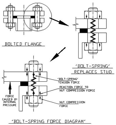
In this article a bolt is referred to as a ‘bolt-spring’. The 'bolt-spring' must pull the flanges together more than the forces acting to push them apart. If the ‘bolt-spring’ is too loose, the pressure stretches the bolt and the flange leaks. To prevent the flanges separating, the bolts are preloaded (stretched). Bolt torque figures are calculated to produce a bolt stretched to at least 65% of its yield strength. Yield strength is the stress at which the bolt shank starts to deform permanently (Take it beyond this & it will snap off.).
A gasket is not a gasket
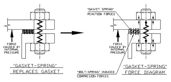
When a gasket is sandwiched between flanges it behaves both as a seal and a spring. The sketch below is the same as the previous except the gasket is now turned into a spring like material. In this article it will be referred to as a ‘gasket-spring’. A 'gasket-spring' will creep with time or temperature. Gasket creep is the gradual deformation (squeezing) of the gasket when sandwiched between flanges. The spring tension in the gasket slackens off. Gasket creep may require that flanges be re-tensioned periodically. It is often necessary to check the bolt manufacturer and the gasket manufacturer torque tables to select the highest torque to be used.
To prevent a flange leak there are a few things to check. The following table will provide some guidance.
WHAT IS REQUIRED
WHAT YOU CAN DO
The bolt-spring shaft ought to be stretched to 75% - 80% of the material yield and more than the maximum bolt load.
Ask the bolt manufacturer for the maximum bolt torque and the number of turns from snug to achieve this or use load-indicating washers. As a last resort use a top-quality tension wrench to the bolt manufacturer's torque specification.
Bolts of sufficient tensile strength to take the process and bolting forces.
Check the bolt head forging marks against the bolt head manufacturer's standards to ensure the bolts and nuts meet the load requirements for the service.
Bolt tension must allow for cycling of loads, shock loads, shear loads and vibration.
Swap the bolt for one of higher tensile strength and pull it up tighter. Make sure all the bolts are to the same rating and diameter.
When pulling up bolts try to apply the torque evenly and continuously.
Lubricate the bolt threads lightly and follow the recommended bolting-up sequence.
Clean, flat flange faces
Check both flanges are clean and flat. Put a steel straight edge or ruler across each face and make sure the faces are flat. Machine flange faces that are not flat and leave enough thickness to still comply with pressure code requirements.
Use washers under the bolt head and nut.
The washer acts to distribute the load evenly and remove the effect of high spots under the head or nut causing uneven bearing on the flange.
The gasket must be suitable to retain the pipe contents and have negligible gasket creep.
Chose the thinnest gasket possible with high seating pressure requirements. Always use a new gasket.
Cut a neat, close tolerance gasket to completely cover the flange pressure face.
A gasket must completely cover the pressure faces to ensure the flange loading evenly squeezes the gasket.
Check the flange is set-up correctly on the pipe.
The flange faces must be square and flat to each other and in-line. The flanges must line up to within 0.01 mm (0.005”). Bowed, twisted, skewed on the pipe, or misaligned flanges it must be removed and replaced properly else sealing is jeopardised.
Tightening the bolt and nut
Tightening bolts by ‘feel’ is the most inaccurate method to use. Because everyone has a different ‘feel’ the likelihood of error is 35%. Using a torque wrench has a 25% error. Number of turns from snug a 15% error. Using load indicating washers a 10% error. Measuring change in bolt length has 5% error. Measuring bolt stress is the most accurate method with a 1% error.
The sketch below gives you an idea of how to gauge torque. Torque is the measure of twist produced by a force applied at a perpendicular distance from the point of twist. The sketch shows an 80 kg man standing on a one-meter long horizontal bolt spanner. This man is applying about an 800 Newton meter (Nm) torque (80 kg x 10 m/sec2 = 800 Nm. But this is at sea level under full gravity, in outer space, where the man would have no weight, he could not apply a torque by this method). If the spanner were 500 mm long (half the previous length) the torque would be 400 Nm and if it were 300 mm long, the torque would be about 250 Nm.
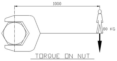
The assembly torque recommended for high tensile 20 mm bolts to give 75% yield stress is about 550 Nm. A man tightening a 20 mm diameter flange bolt with a 300 mm, or even a 450 mm, long spanner would probably not generate enough force to properly tension the bolts. On bolts of 20 mm diameter and larger, depending on the pressure in the pipe and the type of gasket, it may be necessary to use an extension arm on the spanner or a hydraulic nut tensioner to get the needed torque.
Bolt thread surface finish
Note that the surface finish of the bolt and nut threads also affects the amount of torque needed to preload (stretch) the bolt. A dry galvanized bolt thread produces more friction between bolt and nut threads than one that is nicely machined and oiled. Tightening on dry galvanized threads would get less stretch in the bolt than tightening on a machined and oiled thread for the same amount of torque. Tables are available that give factors by which to increase or decrease the manufacturer's recommended bolting-up torque. They vary from 2.1 for a dry galvanized thread to 0.7 for a nicely machined and oiled thread.
Bolting up sequence


Hover over animation above for bolt tightening sequence chart.
The bolt tightening sequence chart above of blank flanges with flange bolt holes shows the sequence to adopt when tightening flange bolts. Lightly lubricate the bolt threads after de-burring them. Insert the bolts into the flange holes and start by pulling-up all bolts finger tight. Then in the torque sequence order shown, tighten the bolts to half torque, again in the order shown, tighten the bolts to the final torque, finally go back over all the bolts, in the torque sequence order shown, and re-torque them again to the final torque to confirm all are correct. This method will sandwich in-place and torque sequence the 'gasket-spring' evenly.
2.3 2.3 Threaded connections
Thread design principles
Figure No. 1 is a cross-section of a parallel thread profile. To prevent threaded parts from binding on their mate, the female thread is cut slightly larger than the male thread. This provides clearance, which prevents clashing. The necessary differences in size and shape create a cavity between the top of the male thread and bottom of the female thread. These cavities spiral all the way along the thread. As the joint is tensioned the clearances produce a gap between the back flank of one and the front flank of the other. The flank gap also spirals the full length of the thread.
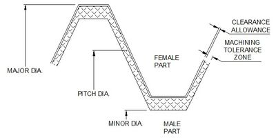
How threads work
Threads allow one component to rotate and travel along the other until it comes up against a solid stop. Once stopped the application of an additional tensioning torque locks the thread flanks against each other and stretches the components like a spring. The spring force jams the two threads into place and binds the parts together. If the tensioning torque is excessive the induced stresses exceed the yield stress of the material and the threads strip or the part snaps. If the torque is insufficient the threads lose their spring tension and the components separate.
The thread shape and size influence both the tightening and ‘break’ torque. The longer the pitch of a thread the greater the mechanical advantage and the easier it is to turn and correspondingly to loosen. As the pitch comes smaller the thread becomes self-locking. A small thread angle form reduces the mechanical advantage and requires more effort to turn than a wide-angle thread form. As the thread angle becomes steeper the thread becomes self-locking.
Sealing cavities in treaded pipe
Pipe threads are closer pitched and of steeper thread form than a bolt and nut of the same diameter. The close pitch and steep flanks act to prevent the joint loosening. To aid with sealing the threads can be made tapered so the two parts are forced mechanically together as one screws into the other. Also, the thread root radii can be altered to produce a clash to make a seal. Such designs still do not guarantee a leak-free joint. They may seal off the root gap, but they still leave the flank gap.
The root and flank cavities along the pipe thread will be a pathway for leakage unless they are sealed. A threaded joint requires sealant to close off the cavities between the male and female parts.
Thread sealant properties
The thread seal will need the following properties to stop leaks.
- Permit dynamic movement of the joint and not fail. The inside and outside of a joint will see different temperatures and pressures and move different amounts. The pipe will vibrate and so will the joint.
- Be chemically compatible with the pipeline contents and the metal of the thread.
- Permit the necessary torque to pull-up the joint while acting as a thread lubricant.
- Slip between tight clearances that remain when the pipe joint is made.
- Not crack, shred or be pushed out of the cavity to produce a leakage path.
- Stop very low viscosity (very slippery) gases, like oxygen and ammonia, from squeezing pass.
- Attach itself to the metal surfaces of the threads and make a bond.
- Still be able to remove the parts when necessary.
Issues with threaded pipe connections
Threaded pipe joints are not suitable for high pressure gases or where the contents of the pipe are flammable. They need to be replaced by ferrule connections (like the fittings from Swagelok or Hoke) in which metal cones are mechanically forced together and deform into each other to seal off the pipe contents.
Teflon thread tape is not a universal thread seal for pipe joints as it shreds and can block fine pilot holes in instruments. Being a plastic it can be deformed by high pressures and allow fluids to be forced pass. Teflon thread tape can insulate one thread from the other and prevent static earthing through the pipe. Be sure you know in which direction to roll-on the threading tape, as it will unwind or ride-up the tread when screwing the fittings together if put on in the wrong direction.
Danger - mixing metal & plastic fittings
Beware of metal threaded fittings in plastic lines or plastic threaded fittings in metal lines. Plastic will creep and is easily deformed; it is attacked by the oxygen in the air and by ultraviolet light; plastic has a different, greater coefficient of expansion than metal. These different properties make the likelihood of leaks at metal-to-plastic treaded connections almost a certainty over the years. If you must connect plastic to metal use a flanged joint of suitable pressure rating. Even with a flexible sealant between the two materials it is likely that over years of service many connections will leak.
Plastic threaded fittings
Plastic threads are usable only in low-pressure service where they will remain at a constant temperature. If you are looking for 50 years of trouble-free life from above ground reticulated gas plastic piping be sure all plastic connections are welded or flanged, not threaded.
Mixing pipe fittings and compatibility
Using pipe fittings made of different metals can lead to galvanic corrosion of one of the parts. One item will eventually fail and leak. Check the galvanic series for both parts and only use different metals if they are very close in the series.
It is also necessary to check the chemical compatibility of mixed threaded fittings to insure they will handle the chemicals and conditions in contact with them. Mixing brass fittings with stainless steel or steel fittings will lead to danger and failure in the wring chemical environment.
Different coefficients of expansion between threaded parts can produce high stress in one or the other at high temperature and a gap between the two at low temperature.
Don’t mix thread standards. BSP and NPT are totally different threads and must never be forced together. They have different flank angles and except for the 1/2” and 3/4” sizes, they have a different pitch. They are not compatible. If you have a job with mixed threads make sure that you go and get the right fittings or the right adapter fittings. Good practices always save a lot of problems in the future.
Pressure test piping
Always pressure test threaded pipe work to 1.25 times its working pressure before putting it into service. While the piping is under pressure, go around to all the threaded joints and ‘soapy water’ test them for leaks. Spray on a mixture of water and liquid detergent and look for bubbles forming as the air leaks out. If bubbles appear remake the joint.
Once installed repeat the ‘soapy water’ test every 36 months as a regular preventative maintenance routine on all threaded gas and air pipelines.
2.4 Chain and sprocket drives
Chain drives involve the use of roller chain to turn a driven sprocket connected by the chain to a driving sprocket. They are used when precise speed ratios are required between the driver and driven shafts. A chain drive allows no slippage. An example is on a gearbox driving a conveyor. Chain drives are also used when a large amount of power is required through the drive. For example, the drive on large rotating kilns.
Roller chain gets its name from the rollers that sit on the bushes of the chain link. The roller turns on the bush and so reduces rubbing friction with the sprocket teeth. Figure 1 shows the components of roller chain. Roller chain is available in numerous sizes and pitches. They come in single, double, and triple stand configuration (simplex, duplex, triplex). Using multiple strand chain allows higher power transfer for the same diameter sprocket.
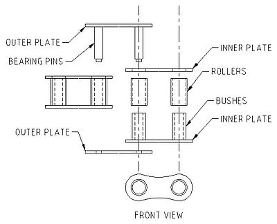
The speed ratio and power to be transferred usually decide the selection of a chain and sprockets. Close pitch for low power, high speed applications and large pitch for high power, low speed applications. The angle of contact between the chain and sprocket should be a minimum of 120o. The smaller sized socket should never have less than 19 teeth because of the high accelerations produced between the rollers and the teeth as they rotate.
Since chain will not easily break, using it increases the risk of breaking shafts or gearbox housings if an overload or jam occurs. When using chain drives it is necessary to protect against overload conditions. Overload protection can be in the form of motor current detection and cut-off of power, mechanical shear pins, which break when loads become excessive or slipping clutches within the drive sprocket, that are set to slip at a predetermined torque. The important thing is to protect the expensive components of the drive train if they become overloaded.
To prevent gearboxes being ripped off their feet orient them, so the chain tension forces the gearbox to be pushed against its mounts. Cast iron gearboxes do not like to be in tension and a sudden overload can shear the housing off its feet. Once the feet on a cast gearbox are broken off, welding can never properly repair them.
Chains and sprockets are normally lightly lubricated. The lubrication must get into the pins, bushes, and rollers of the chain. The sprocket teeth wear as the hardened rollers on the chain rub against them while the sprocket turns. Lubrication reduces the friction forces against the teeth and roller. The only time lubrication is not applied is in dusty environments. In dusty conditions the chain and sprocket are left dry otherwise the dust mixes with the lubricant and forms a grinding paste that wears the teeth away faster than if they ran dry.
The other way in which chains wear is by links stretching. Chains experiencing high loads or surging loads tend to gradually stretch. Usually, the link pinholes elongate. As the chain lengthens, its pitch alters, and it no longer meshes properly with the sprocket. When chains start jumping sprocket teeth it is likely the chain has stretched. Some stretch is acceptable (maximum 2%) and any slack is usually taken up by moving the shafts further apart or by using a jockey wheel on the slack side.
Chains should be used in the vertical orientation. If they are used horizontally, they will sag over the distance between the sprockets. The sag will cause the teeth and chain to wear on one side and require replacement.
The greatest destroyer of chains is dust and dirt. In the presence of a lubricant the two form a grinding paste which abrades rollers and side plates. Ensure the local atmosphere is clean and no dirt or water can find its way onto the chain.
Change out all sprockets and chains in a drive train if a chain or sprocket needs replacing. If you use new parts with worn old parts they will quickly wear into the shape of the old part.
Torque limiting
In overload situations it is necessary to protect the equipment from major damage. One option is to size the chain, so it purposefully snaps, it is also practical to install shear pins through the sprocket and shaft that shear through when the drive is overloaded and allow the sprocket to spin on the shaft. A third option is to install a torque limiter clutch within the sprocket.
The clutch has internal surfaces that are forced together and drive the shaft under normal load conditions. But when overloaded the clutch slips and the sprockets do not drive the shaft with as much force. This function is also useful on sudden start-ups and allows the shaft to come up to full speed slowly as the friction on the clutch permits gradual speed up of the shaft.
2.5 V-belt and pulley drives
A friction drive connects two shaft-mounted pulleys by a belt that is drawn taut enough to grip each shaft and turn them. The belt is pulled tight to create friction with the pulleys. As the drive pulley turns, the belt moves the connected driven pulley.
Friction drives
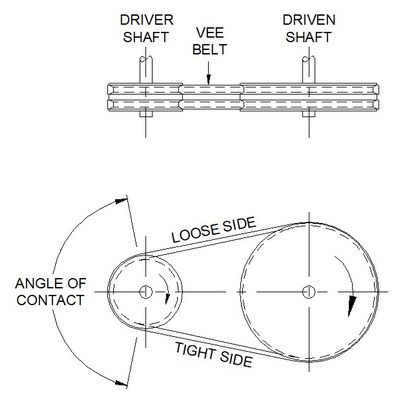
The success of the drive depends on maintaining frictional contact between belt and pulleys. V-belt drive friction is dependent on several factors. These are –
- Tight side and loose side belt tensions.
- The coefficient of friction between the belt material and the pulley material.
- The total angle of contact around the pulley, which depends on the pulley diameters and their distance apart.
- The centrifugal force lifting the belt off the pulley produced by the rotation of the pulley.
- The angle of the V in the pulley which acts to wedge the belt in place. It is usually between 17o and 19o.
The advantages of V-belts
V-belts offer several advantages in their use.
- Easy, flexible equipment designs, as tolerances are not critical.
- Reduce shock and vibration transmission.
- Changing pulley sizes changes the driven shaft speed.
- They require no lubrication.
- Maintenance is easy provided unrestricted access is available to the drive arrangement.
- The pulley alignment is quickly done with a straight edge or a string line spanning across both pulley faces.
- Setting the belt tension is readily achieved by jacking the pulleys apart and measuring the transverse distance the belt can move.
- Higher shaft torsional loads are handled by using multiple belt pulleys.
- In an overload situation the belts slip, and the equipment is protected.
- A jockey pulley can be installed to increase the angle of contact and allow transfer of more power. It can be mounted on either the tight or loose belt side and adjusted inwards to provide more angle of contact.
The belt
Conventional V-belts are made of rubber reinforced with imbedded plastic, fiberglass, or steel cords. The cross-sectional area of the belt depends on the power to be transmitted through the belt. Multiple belts are used in combination to transmit large amounts of power.
The pulley
Pulleys can be cast iron or steel. The V groves are machined into the solid billet. The pulley is usually keyed to the shaft. They must be balanced.
Issues to consider when using V-belts
When using V-belt drives there several issues to address.
- Belts in multiple belt drives may need to be a matched set. A matched set of belts means each belt is of equal length so they all take equal loads. In an unmatched set the shorter belt is more heavily loaded and fails soonest.
- Rubber has a limited life. Oxygen in the air, heat, dirt, and oil deteriorate it while tight bends and the loads carried through the fibers of the belt stress the rubber.
- Dirty, dusty conditions destroy both belt and pulley. Dust settles on the pulley and imbeds into the rubber. Eventually the belt starts to slip thereby polishing the pulley and reducing the friction between belt and pulley. It may be necessary to install a ventilated, dust proof enclosure around the equipment. This is often the case for belt driven air compressors in dusty locations.
- Belt life is limited, and they will fail by stretching, snapping, or slipping when their working life limit is reached. Drive belts and pulleys should be inspected on a preventative maintenance routine or replaced prior the likely end of their working life. Replace a stretched, cracked, or shiny belt immediately.
- Provide pulleys of generous diameter so the belts are not excessively flexed. Flexing around a small pulley produces high stress gradients across the belt.
- Determine the optimum number of belts for a drive so they are loaded to the manufacturer’s recommendations.
- The separation distance of the pulleys determines the angle of contact the belt makes with each pulley. If the separation distance is too close the driven pulley will not have enough belt in contact with it to develop the required driving friction.
- When the pulley V faces become polished the pulley must be replaced. It is possible reclaim the pulley by lightly machining the groove.
- As more belts are added to the drive and tensioned to the required load the driven and driver shaft bending loads increase. This will raise the radial loads on the shaft bearings nearest the pulley and act to reduce their working life. Ensure the shaft bearing type selected can accommodate high radial loads.
- For safety reasons the belts and pulleys require a guard over them. The guard must be well ventilated and not allow heat from the motor or working equipment to be trapped and overheat the belts. Provide plentiful access and make removal of the guard easy.
- Belt tensioning testers are available to check the amount of tension applied to the belt meets manufacturer’s recommendations.
2.6 Mechanical seals
Mechanical seals are used to keep the bulk contents of rotating equipment such as pumps and compressors from escaping. They do this by sealing the shaft that protrudes from the casing. They require quality installation and operation conditions for a long life.
The sketch below shows the basic construction of a simple, single mechanical seal.
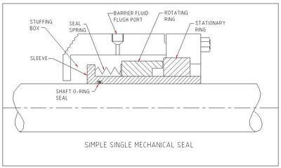
The harder stationary ring is held in place and the softer rotary ring rotates with the shaft. Springs or a convoluted bellows (rubber or metal) pushes the rotary ring against the stationary. With the faces sealed together as they turn, no path exists for the bulk contents to escape.
Between the seal faces an extremely thin layer of product or seal flush fluid develops and acts to lubricate and cool. This thin layer prevents rubbing contact of the surfaces, without which frictional heat would rapidly destroy the seal faces.
WHAT CAUSES A MECHANICAL SEAL TO LEAK?
Mechanical seals leak when the faces are forced apart. If there is evidence of product leaking from a mechanical seal, then the faces have had cause to separate. The challenge to maintainers is to find the cause and rectify it. Below are some of the common causes of face separation.
1. Pressure hammer within the equipment caused by such occurrences as rapid closure of valves somewhere in the process.
2. Solids/dirt pinned between the seal faces during assembly or during a pressure surge.
3. Crystal build-up on the seal faces as crystallising products seep past the running faces.
4. Seal faces run dry and build-up heat and crack due to nil or poor lubrication.
5. Under-loaded springs/bellows pushing on the rotary seal when the seal was set-up on the shaft.
6. Unequal spring force on the rotary seal due to damaged or jammed springs/bellows.
7. Movement of the rotary seal housing along the shaft if the locking screw loosens.
8. The seal was damaged during installation and not corrected.
Requirements for long seal life
To get a long life, mechanical seal faces must be kept clean, cool, lubricated, square to the shaft and flat together.
Achieve a healthy local environment
Use a barrier fluid to clean, cool and lubricate. These first three requirements are best achieved by pressurizing the spring/bellows chamber with a suitable clean, cool barrier fluid at a pressure higher than on the process side (stuffing box) of the stationary seal. The barrier fluid can be a liquid or gas depending on the service required of the seal. Usually, a pressure difference of 100 kPa (15 psi) is sufficient to guarantee slight weeping across the seal faces from the barrier fluid into the process. As a rough rule of thumb, the stuffing box pressure is about two-thirds the discharge pressure.
An exception to use of a barrier fluid is when the fluid being pumped is itself clean and non-threatening to safety and the environment. Products such as clean water do not need a barrier fluid because the centrifugal action of the spinning seal will draw in minute amounts of water that will cool and lubricate the faces. This water escapes as vapor to atmosphere.
Achieve precision assembly
Quality seal manufacture and installation achieve the last two requirements. Mechanical seal faces are manufactured to a flatness that is measured using wavelengths of light. Such fine tolerances imply high precision equipment. Therefore, seals reconstructed in maintenance workshop conditions never last. Precision manufacture requires a precision environment.
High precision is normally only possible at the time of manufacture. Mechanical seals installed by the pump manufacturer tend to last longer than seals installed in the same pump when on-site. The growth in the use of cartridge seals reflects a growing awareness of the importance of precision in the construction and installation of mechanical seals.
Achieve precision running
The alignment between the centre lines of motor and pump, for 4 pole motor speeds and less, must be perfect to within 0.050 mm (0.002”) from the end of the motor shaft to the end of the pump shaft when at operating temperature. There must be no vibration of the mechanical seal due to poor balance, poor tolerances, poor operation, wrong usage practices or poor installation.
Everything must be done to keep the mechanical seal faces together. The seal faces must be always square to the shaft. The shaft can only deflect a maximum of 0.025-mm (0.001”) at the mechanical seal face. The shaft and seal centerlines must be concentric to 0.025-mm (0.001”). If the entire shaft rocks and sways the seal must move with the shaft. If necessary, mount steady bearings close to the seal to ensure the shaft and seal remain concentric. Shaft overhang must be kept small and if that is not possible a thicker shaft or one made of stiffer materials or design is required.
What to do to extend seal life.
The working life of a mechanical seal should be at least five years. Lives of ten years have been achieved in clean, carefully controlled and monitored applications. People involved in the operation of equipment with mechanical seals need to be aware of the following:
OPERATORS
MAINTAINERS
Pressure hammer problems need to be found and fixed.
Ensure a clean flushing product or barrier fluid is provided to the seal faces.
Keep the barrier fluid pressure slightly higher than the stuffing box pressure.
Make use of valves and pressure gauges to regulate the flow.
Run the pump at design flow and pressure. Never deadhead it.
Align shafts to near perfection at the operating temperature.
Have mechanical seals repaired by authorized repairers.
Follow the manufacturer’s instructions during installation.
2.7 Soft-foot distortion
This topic is provided by – Is Your Equipment Feeling a Little Out of Kilter?
A lesson on Soft Foot by John C. Robertson, Strategic Work Systems, Inc. swspitcrew.com
What is soft foot? One of the most overlooked machine problems, soft foot describes a machine’s foot that deflects a small amount when the hold-down bolt is tightened.
Imagine a person sitting on a three-legged bar stool that has one leg shorter than the other two. If that person moves his weight slightly, the stool tips in the direction of the short leg and is very uncomfortable--even dangerous. The solution is simply to pack sufficient shims under the short leg until it gets back on an even setting. This situation is also very common with machinery seating.
Check each hold-down foot of the driver and driven units for a soft foot condition. If a soft foot condition exceeds +/- 0.002", corrections must be made to ensure that the unit sits squarely on the bed plate with no stress.
Soft foot problems come in many different forms, some more obvious than others. These are:
Parallel air gap: One leg is too short or one base plate mounting pad is not level with the other three. This can also be caused when the shims under one foot are the wrong size.
Bent foot: The bottom of one foot is not parallel with the base.
Squishy foot: Dirt, grease, paints or rust, bent or burred shims, or too many shims are found under the foot. Feeler gauges should be used to measure the clearance all around the foot’s three exposed edges.
Induced soft foot: Two soft-feet are located on the same side or same end of a machine, and the feeler gauge indicates a gap that is parallel or nearly parallel.
Gaps without soft foot: There is a visual gap under the foot before tightening, and there is none after tightening. A laser check might indicate a relatively small soft foot, but feeler gauges will indicate a much larger gap. Installing shims is not the answer to this problem. The most logical thing to do is to machine the base plate or the machine housing.
There are also external forces that can cause soft foot. Some of these are:
- Overhung machines or attachments
- Belt, gear, or chain loads
- Hoses or stressed conduit
- Structural bracing attached to the machine
- Jack bolts left tight against the machine base
- Poorly finished foundations Piping that does not meet zero-cold-spring tolerances at flange connections
Each machine foot location on both the driver and driven units must be individually checked for the existence of soft foot. If a soft foot movement is observed to be greater than +/- 0.002", it must be immediately corrected. The checkout procedure is as follows ...
- Visually check all the machine’s feet for breakage, cracks, or bent feet. If these defects exist, they must be corrected before soft foot checks are made.
- All shims that are rusted, dirty, and have been burred at the edges must be replaced with correctly dimensioned, pre-cut stainless steel shims.
- Using a feeler gauge, or taper gauges, determine the gap between the bottom of the foot and the bed plate. Ensure that the gauges do not touch only at one point. In many cases, machine feet can suffer from a compound bend, which produces angular irregularities and creates a tapered gap. If the foot cannot be straightened, tapered off shims must be fitted to correct the condition. Always perform a three-point check at all the three edges of the feet when investigating soft foot conditions.
- Placing a magnetic based dial indicator stand on a stationary location (usually the bed plate) and ensuring the indicator dial stem button is contacting the machine foot surface makes this check. The dial indicator face is calibrated in thousandths of an inch increments, and when the stem is pressed in toward the dial, the needle rotates in a clockwise, or positive (+) direction.
All measurements taken in that mode will be preceded with a + sign. The indicator dial stem is depressed onto the shaft surface enough to rotate the needle (pointer) approximately one revolution. It is then set to 0.000". The hold-down bolt’s nut is slackened, and the deflection of the needle is carefully recorded. The hold-down bolt’s nut is again tightened to the specified torque value. This procedure is carried out at all the machine’s feet, and all readings are recorded for comparison and determination of any soft foot conditions.
The machine foot, or feet, which exhibits the largest movement, and the greatest measurement, needs shimmed to correct the discrepancy. If the measurement was 0.008", a shim thickness of 0.004" should be inserted under that foot as an initial start in correcting the soft foot. The bolt would be torque tightened, the dial indicator would again be set up and adjusted to 0.000" before slackening off the bolt, and the new measurement would be recorded. This procedure would be repeated until the soft foot condition disappears. A final all-round check is again made before signing off the job to ascertain the accuracy of the correction. All hold-down bolts must be left tight before closing this inspection.
The number of shims needed for correction of soft foot and alignment must be kept to a minimum. If, for example, 0.100" was the required depth of shims, you should install one 0.090" shim and maybe one or two other shims to make up the difference. Each successive shim layer is a potential soft foot cause if air or liquid is trapped under each shim.
Soft foot is one of the most overlooked machinery problems. It will distort heavy machine casings badly enough to cause the machines to fail through shaft misalignment, bearing failures, and mechanical and gear wear. The problem is often found to have originated in the initial installation, which was assumed to be done correctly because the manufacturer's representative set it. Always check for soft foot before making any shaft alignment adjustments. You will never regret the little extra time spent on this important task.
2.8 Shaft alignment
Shaft misalignment is one of the most common reasons for bearing and mechanical seal failures. Rotating misaligned shafts produce vibration and complex fluctuating radial and axial loads that lead to breakdowns. Shaft alignment is a precision maintenance requirement that requires exacting care and detail and if not performed will cause much production down time.
Misaligned shafts are the single greatest reason for failure of rotating equipment and connected components. When misaligned shafts are coupled together each shaft rotates about a different centre and has different orbits. If the two shaft positions in the orbits are not directly opposite each other the coupling is distorted. The coupling reacts to the distortion by pulling or pushing each shaft and which produces fluctuating forces throughout the equipment.
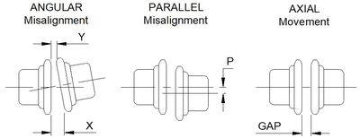
The axial, radial and bending forces developed by the ‘push-pull’ action, and the resulting non-circular shaft motion, is transferred through to bearings, shaft seals and, in pumps, to the mechanical seal. Vibration, fatigue, and unnecessary damage result. The motion that causes the most damage is axial movement of the shaft. This is because parts are clamped together one against the other and there usually is little allowance for axial movement. Figure 1 shows the types of misalignments.
To prevent rapid failure of equipment the shafts must be purposefully aligned to within very close tolerances. A simple way to look at it, for 4 pole motor speeds and slower, is that the centerlines of aligned shafts must be within 0.050 mm (0.002”) along their full length at operating temperature.
Machine Speed
Max Offset at Machine Feet
Max offset at Coupling Centre line
Up to 1500 rpm
0.050mm (0.002”)
0.025mm (0.001”)
Over 1500 rpm
0.025mm (0.001”)
0.013mm (0.0005”)
Table 1 Alignment Tolerances for Rotating Equipment
Table 1 above ↑ shows alignment tolerances recommended by specialists after compiling equipment reliability data over many years and industries.
Figure 2 below ↓ shows an overhead view (plan view) of how Table 1 is applied.
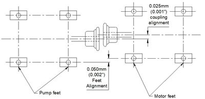
This approach of aligning the whole machine guarantees parallel shafts and accurate coupling alignment. The common practice of measuring between and across the coupling faces can produce a coupling within alignment tolerance but with back ends on both machines still skewed.
The causes of misalignment
To prevent misalignment becoming a serious cause of equipment failure it is necessary to understand why it occurs so it can be corrected. Table 2 lists the most common causes of misalignment and explains what to do in each case.
CAUSE
REMEDY
Insubstantial foundations, bases and hold down bolts.
Concrete foundation mass must be 5-times the mass of the equipment it supports. This is usually only possible if the plinth is formed in the floor. Base plates must be thick and stiff to prevent distortion when the equipment applies torque. Typically, thicker than 20 mm (3/4”). Hold down bolts must be bonded to the concrete and not just held in place by friction. Hold down bolts must stop the equipment flexing. On 2.2 - 11 kW drives use 16 mm diameter bolts, from 15 - 75 kW use 20 mm bolts, for 100 kW and above use 25 mm bolts.
Machine components damaged, poorly made and worn.
Make sure looseness in bearings that cause shafts to rattle and rotate off centre is taken-up. Replace bent shafts. Bore couplings on-center making sure the bore is parallel with the hub and square with the face so there is no run-out (wobble) as it turns. The bore machined into a coupling must be central to within 0.02 mm (0.001”).
‘Soft-foot’ (‘spongy’ support) at the machine feet.
‘Soft-foot’ is the term used to describe the situation where the machine support feet do not all make complete and even contact with the base plate or frame on which it sits before the hold-down bolts are tensioned. It is easy to pull a foot down with the hold-down bolts, but the result is a bent and twisted machine with bent and twisted internal parts. A machine bent out of shape will fail before it should. Use 316 stainless steel shims (plastic is too soft and mild steel– rusts) under each foot so the foot is positioned ‘naturally’ and the hold down bolt can keep the foot in its ‘natural’ location.
If you would like to reference this guide offline, and/or print copies for your maintenance, operators, or students in your facility, you can purchase a PDF version of this guide below.
10 more Mechanical Maintenance Technician Best Practices ...
<< Back to chapter 1, Engineering Principles for Maintainers and Operators


