Rotating Machinery Services
Rotating Machinery Reliability Essentials Whitepaper
By Mike Sondalini

The Rotating Machinery Reliability Essentials whitepaper is written for consumption by beginning mechanical engineering students and maintenance personnel. (Rotating machinery is referring to machinery with rotating or reciprocating parts.) Mike covers topics on tracking large rotating equipment and starting under a load, gearboxes, agitator shafts, vee-belts and chain drives, and even electric motors. Also included are topics from the Bearing and Lubrication whitepaper. This white paper is 45 pages.
The knowledge and experience shared in this whitepaper is great for those considering rotating machinery services, and help build a foundation for rotating machinery testing. This one can also can be used to supplement applied tribology training related to rotating equipment. Mike shares application knowledge of vibration testing and control, shaft alignment, as well as long-life reliability.

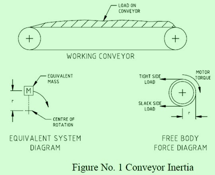
To bring a machine up to full speed from rest requires a force to be applied (Newton’s second law of motion). For rotating machinery the force is applied as a torque. Torque is a linear force acting at a certain distance from the center of rotation. The free-body diagram in Figure No. 1 shows the inertia force acting at the head pulley drum. The motor that drives the conveyor will need to generate slightly more matching torque if the conveyor is to move.
Rotating Machinery Reliability Essentials - Contents:
Tracking large rotating equipment.
Rotary dryers, kilns, mills, and reactors turn on tires and trunnions. Each tire is mounted to the rotating shell and revolves on two roller trunnions. If the alignment between the tire and trunnions is lost due to wear, poor repair, installation error, or impact, the equipment will need to be tracked.
Vibration and out-of-balance equipment.
Vibration from out-of-balance rotating equipment can be frightening. The ground shakes, machines jump about, hold-down bolts come loose and parts break. An unbalanced rotating body will produce forces on its bearings and transmit them throughout its structure and into the foundations.
Vibration and its control.
Vibration in equipment is the result of unbalanced forces. Out-of-balance is corrected by adding or removing material so that when the equipment is operating the unbalance is controlled to an acceptable level.
Keep gearboxes running.
A gearbox is used to control the operating speed of industrial equipment. Proper selection, care, and maintenance of gearboxes are critical. Failure of the gearbox causes the equipment and associated plant to stop.
The importance of fit, tolerance and clearance.
Many equipment breakdowns and stoppages occur because of improper sizing between holes and shafts. The shaft is too tight in the hole; the hole is off-center; one part is loose on another and slips out of place or does not seal as it should.
Agitator shafts steady bearing problems.
Vertical tank agitator bearings are required to take both radial and thrust loads. To protect the gearbox it is common practice to install intermediate bearings on the shaft. If these bearings are exposed to the process vapors then special care is needed to protect them from contamination and ensure adequate lubrication.
Shaft alignment on pumps.
Shaft misalignment is one of the most common reasons for bearing and mechanical seal failures. Rotating misaligned shafts produce vibration and complex fluctuating radial and axial loads that lead to breakdowns. Shaft alignment is a precision maintenance requirement that requires exacting care and detail and if not performed will cause much production downtime.
Shaft coupling selection issues.
Shaft couplings are used between shafts to connect them so power can be transmitted and to allow for axial expansion. Shafts can either be aligned or intentionally inclined at an angle to each other. When at an angle a universal joint is used to connect the shafts. When directly aligned a shaft coupling is fitted.
Bronze - use the right one for the job.
Here we talk a little about bronzes, their properties, and applications. Occasionally people refer to a brass bushing, when in fact they want a bronze bushing. Also Mike focus on a range of brasses and bronzes which are available. Wrought products are factory produced by rolling and mechanical working while bearing bronze castings are usually by one of the following techniques ...
Electric motor problems.
Here we cover a basic explanation of electric motor construction and operation along with twelve problems that can be encountered with their use. Most electric motors in industrial equipment are three-phase alternating current induction motors. Induction is the creation of an electric current across a gap. Two types of induction motors are commonly used: squirrel cage and wound rotor. The names come from the way they are built.
Vee-belt drives.
Here we cover some basic theories of friction drives and list 11 factors to be considered when using vee-belt drives. A friction drive connects two shaft-mounted pulleys by a belt that is drawn taut enough to grip each shaft and turn them. The belt is pulled tight to create friction with the pulleys. As the drive pulley turns, the belt moves the connected driven pulley.
Chain drives.
Chain drives involve the use of a roller chain to turn a driven sprocket connected by the chain to a driving sprocket. They are used when precise speed ratios are required between the driver and driven shafts. A chain drive allows no slippage. An example is a gearbox driving a conveyor. Chain drives are also used when a large amount of power is required through the drive. For example the drive on large rotating kilns.
Spread forces through equipment & reduce breakdowns.
When a force is applied to a structure it reacts by deforming slightly. The structure is placed in a state of strain. The strain produces internal stresses. If there is insufficient strength in the structure to take the stresses it will fail. Equipment failures involving sudden breakage of parts will most likely be traced back to overstressing of the part.
Electrical motor current protection saves your plant.
A lot of equipment failure results from just simple, plain mistakes, sometimes from unintentional forgetfulness, sometimes from 'short-cut' taking, and sometimes because of ignorance of the consequences. The result is the plant is destroyed at great cost and inconvenience. But for a plant being driven by an electric motor use of under and over-current protection is something that can be done very cheaply to protect it from being run outside of its design 'envelope'. A current transformer is placed around the electrical cables leading to the motor. The transformer is connected to a monitoring device that alarms when the current is outside preset limits.
Setup tank agitators gearboxes for a long-life at low cost.
Agitated vessels and tanks are common throughout the process and chemical industries. A properly sized agitator with the correct proportions to suit the tank will deliver a well-mixed product. A correctly sized gearbox with well-chosen bearings and bearing arrangements will need only regular lubrication while giving years of trouble-free service.
Rolling bearing vibration detection.
Roller-bearing vibration measurement is one of the major condition monitoring tools in regular use. By measuring the velocity, acceleration, and frequencies emitted from a rolling bearing it is possible to tell its condition and the likelihood of imminent failure. The technology is well-established and well-proven but requires a good understanding of equipment vibration characteristics before a user can draw good interpretations from the results.
Rotating shafts under bending stress.
It is common to transmit motion using rotating shafts. The shafts are mounted in bearings and turned by force through a drive arrangement. The shafts usually also carry a load. These loads cause bending and the shaft reacts by producing counter stresses within itself. Provided the reactive stresses are within the shaft's strength range it will take the load. But if the stresses are greater than what the shaft can take it will bend. Even if the stresses are below the load limit but fluctuate, it is possible that the shaft will break from fatigue. The point of highest stress can be found by looking at the arrangement of the shaft supports and loads and calculating the forces and stresses.
The big bang - starting and stopping equipment under load.
When a machine starts up its parts move from zero speed to the operating speed in a short time (the reverse when stopping). During this short period the biggest forces that the machine experiences act on its components. If during the start-up or slow-down the product or process loads are added to the machine's own self-loads the forces acting on the machine' parts are horribly magnified. If these impulse forces exceed the machine's design allowance or cause gradual fatigue, then the stressed parts will shatter without warning.
Lubrication cleanliness & filtration.
When oil in gearboxes become contaminated there is a rapid loss of bearing operating life. It is critical that metal particles, dirt, sand, oxidization products, etc be removed from the oil before they gouge and tear-up the finely tolerance machine parts. Oil replacement, contamination prevention and oil filtration are common practices religiously adopted by the best in the equipment reliability management business. This article explains the fine requirements for successful contamination control to ensure long trouble-free equipment life.
Oil - how clean does it have to be?
Clean, dry oil can extend equipment life between failure up to 8 - 10 times the normal operating life. Timken, the bearing manufacturer, reports that reducing water levels from 100 PPM (parts per million) to 25 PPM increases bearing life 2 times. British hydraulics research indicates that if solids contamination with particles larger than 5 microns (0.005 mm or 0.0002") is reduced from the range of 5,000 - 10,000 particles per milliliter of oil to 160 - 320 particles, the machine life is increased 5 times.
Get mechanical seals working properly.
Mechanical seals are used to keep the bulk contents of rotating equipment such as pumps and compressors from escaping. They do this by sealing the shaft that protrudes from the casing. They require quality installation and operation conditions to be reliable.
Protecting bearings from dust & water.
Protecting bearing from dust. Protection methods like labyrinth rings, rubber seals, felt seals, and shaft mechanical seals are described. The choice of the appropriate shaft seal and seal configurations to protect against dust ingress is critical. Numerous shaft seal designs suited to dusty conditions are reviewed.
Converting bearings from oil bath to greased lubrication.
The conversion of shaft bearings on a basket centrifuge from oil bath to grease lubrication involved changing the method of shaft sealing. Roller bearings can be lubricated with oil or grease. The use of grease has distinct advantages in some applications.
Gain valuable insight and understanding; get your copy of Rotating Machinery Reliability Essentials today!
![]() Download right away in a printable PDF format!
Download right away in a printable PDF format!
$12.50
An Excerpt From Rotating Machinery Reliability Essentials
"Tracking Large Rotating Equipment"
Unless the equipment manufacturer or installer provided the datum, you need to be creative in establishing the necessary reference points. One method that proved suitable on a rotary reactor was to use laser surveying to establish both the vertical heights of the trunnion pedestals under each tire and to position a datum line offset from the tire axis to provide horizontal reference points. This allowed accurate measurement of the horizontal and vertical position of each tire axis to within 1mm.
Figure No. 2 shows how the hold-down bolts were used as a horizontal reference on the assumption that the pedestals were cast identically and had been properly aligned when the equipment was originally installed. The numbers in the circles represent the vertical datum and show that all but one end of one pedestal were at the same level. The “marks on the concrete floor” distance represent the offset from the hold-down bolts to give the horizontal alignment.
Please contact us with any questions.
