Electric Motor Load Testing:
- Home >
- articles >
- electrical >
- engineering >
- electric motor load testing
The effect of process changes on electric motors.
Where the equipment duty and service is adjustable by the operator, or fluctuates as the process changes.
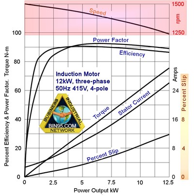
Effect of process changes on electric motors. This article explains the effect of changing process loads on AC induction electric motor performance. The motor’s behavior is a response to the load imposed on it by the equipment connected to it. The equipment’s behavior is itself a response to the duty and service it has to perform. Where the equipment duty and service are adjustable by the operator or fluctuate as the process changes, the motor will react to those changes. When the changes are so excessive that they are beyond the motor’s ability to handle them the motor stops and the equipment or process stops with it.
Alternating current (AC) induction electric motors are a common source of driving power used throughout the industry. The motor shaft is connected to the equipment by a coupling, drive belt, or gear. When electric power is provided to the motor it turns the attached equipment. The equipment is the load on the motor. The load on the equipment is the process
duty it must perform.
For example, a centrifugal pump moves liquid from a low pressure to a higher pressure. Similarly, a fan takes gas in at low pressure and pushes it to a region of higher pressure. The motor provides the necessary electrical energy to drive the impeller or blades that cause the change in the fluid’s pressure energy state. When more fluid is needed (i.e. when
the load increases) the electric motor responds by working harder. You will soon learn how it does that.
If an electric motor is forced to work beyond its ability it will either heat up and burn out or it will overload the electrical supply and cause a fault in the supply circuitry.
Operation of an Induction Electric Motor:
An induction electric motor works when AC power is turned on. Each phase of the alternating current goes into motor windings positioned around the outer stator. The position of the stator windings and the rise and fall of the alternating current produce sequentially rotating electric and magnetic fields inside the stator. The rotor is free to turn inside the stator. Within it, the rotor has metal bars. The stator electric field induces an electric current in the conducting metal bars (like a transformer). When a magnetic field cuts through a conductor carrying an electric current a force is developed in the conductor at right angles to the magnetic field. When the circulating stator field energizes the metal bars in the rotor they are forced to move and the rotor turns (See article 262 Electric motor problems and 334 Electric motor current protection saves your plant).
It is important to understand that there must be relative movement between the conductor and the magnetic field. The force is only developed if the magnetic field cuts the conductor. In a motor, the rotor runs slower than the rotating stator magnetic field. This means the magnetic field cuts the rotor conductors. The difference between the speed of the magnetic field and the speed of the rotor is called ‘slip’.
The greater the difference between the stator magnetic field speed and the rotor speed (the ‘slip’) the more often the magnetic field cuts through the conductor and the greater the force generated on the conductor.
Electric Motor Torque and Power Characteristics:
Because an electric motor rotates it can only deliver torque (a turning force) through its shaft. It also means that an electric motor will experience all equipment loads on it as torque. The motor shaft will turn and the attached equipment will move only as long as the motor can generate the required torque. Figure No. 1 at the top of this page, shows the performance curves for a squirrel cage induction motor (the most common AC motor). They show that as the rotor speed drops because of an increased load the rotor slips more, the torque generated rises and the current draw in the stator increases.
It is also interesting to look at the formulas for electric motor torque and power to see what factors affect each of them. We will not use the formulas except to note the relationship between the current, torque, and power.
Electric Motor Torque Formula
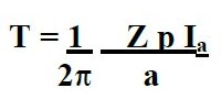
Where ...
T = motor torque _ = flux per pole
Z = active contactor p = number of poles
Ia = armature current a = parallel paths
Electric Motor Power Formula
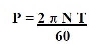
here ...
P = motor power N = revs per minute
T = load torque π = pie (3.142)
The formulas indicate that an increase in power due to an increase in the service load requires a proportionate rise in the torque so it can match the load. This increased torque draws a bigger electrical current into the motor.
Process Load Torque and Power Characteristics:
An electric motor will try and match its torque output with the torque load requirements of the equipment in the process. If the equipment’s load changes the motor will draw enough electric current to make a torque that matches the load.
In order to note what actually happens to the motor when process variables (like flow rate and pressure) change the load, we will use centrifugal pumps and centrifugal fans as examples. Figure No. 2 below shows stylized performance curves for a centrifugal pump (centrifugal fans are a similar shape but the gas pressures are much less than those for liquids).
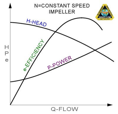
The pump curves in Figure No. 2 for a constant speed impeller indicate that flow and pressure affect each other in the relationship shown by the shape of the ‘head’ curve. If the flow increases by opening valves and dampers, the pressure from the pump or fan falls. If flow decreases by closing valves and dampers the pump or fan pressure rises.
The power needed to turn a pump and produce the required discharge flow rate and pressure is found with the formula:
Power Required Formula
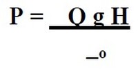
Where ...
P = shaft power _ = liquid density
Q = flow rate g = gravity acceleration
H = head of liquid _o = conversion efficiency
The efficiency factor is necessary because there are losses from mechanical (friction, rubbing, etc), hydraulic (recirculation, eddy vortexes, shock), and volumetric (reverse flows) inefficiencies in the pump.
The formula tells us that for a constant-speed impeller increasing the flow (i.e. a bigger load) requires more power. Similarly, if the flow stayed constant and the pressure increased then the needed power also rises. However, we know from the performance curves that flow and pressure in a centrifugal pump or fan are affected in a reverse relationship and neither stays constant when the other changes.
Effects On The Motor When Flow and Pressure Changes:
We can now use all of the above diagrams and relationships to explain what happens to the electric motor when process flows and pressures change i.e. when loads change.
Changing the flow (i.e. changing the load) through a pump or fan changes the power needed from the motor. From the pump power equation and characteristic curves, it is seen that increasing the flow through a constant-speed pump or fan by opening valves and dampers means more power is needed. While decreasing the flow reduces the load and the power requirements. Conversely increasing the pressure by closing valves and dampers decreases the load on the motor.
Opening valves and dampers lift the load on the motor and closing valves and dampers decrease the motor load. This is only true for a constant-speed impeller. If the impeller speed is variable it becomes more complex to analyze but the principles remain the same.
As the load rises the torque applied to the motor slows it down and ‘slip’ increases. The stator magnetic field cuts the rotor conductors more often. More force is generated on the rotor and the rotor torque increases. From the electric motor graph and formulas, it is seen that as slip increases the motor correspondingly draws more electrical current. The greater the current the hotter the motor gets. If it runs too hot or for too long above its design abilities it will burn out or overload the circuitry or trip out at high temperatures if thermistors are installed in the motor and in use.
When the motor sees a sudden change in load, like an equipment jam or a rapid valve opening, the change in slip is massive and the rise in the torque is rapid. Correspondingly the change in electric current draw is also rapid. The speed and size of the electric current rise can produce an overload and blow fuses, trip circuit breakers or burn motor windings.
Proper Handling of Motor Load Changes:
In all cases, loads on electric motors should be increased slowly and must be less than the abilities of the motor to generate the required torque. If pump or fan motors trip out check that the valves or dampers are positioned to keep flows within the motor’s load capacity. If motors on equipment trip or burnout, then somewhere there must be something causing a big load. Find the load and remove it before again starting the motor.
One way to assist people in monitoring loads on electric motors is to install current monitoring read-outs and set working limits for the motor that is not to be exceeded. People can then monitor the effect on the motor of process flow, pressure, or load changes that they make.
References: A. Mychael, Electric Circuits and Machines Edition 2, McGraw-Hill Book Company
Related Courses:
Motor Controls Certificate Course
Motor Control Centers Online Course
Electrical Troubleshooting Training Course
Related Article:
What do the letters FLA on a motor nameplate stand for?
Electric Motor Current Protection Saves You Plant

