Instrumentation and Process Control Training
- Home >
- articles >
- electrical >
- instrumentation and process control training
Excerpt: Instrumentation and Process Control Book
Differential pressure transmitters:
Below is the Differential pressure transmitters section from the Instrumentation and Process Control training white paper/pdf book.
Differential pressure transmitters. These instruments are used to detect pressure. The sensing element is connected to the process by pipe work and flexes in proportion to the pressure. The resulting distortion produces an electric signal that is amplified and converted to a value on a read-out. Keywords: pressure sensor, strain gauge, tank level, process pressure, pressure difference.
A typical sensing element is a strain gauge of piezoelectric crystal (such as quartz, which produces a voltage across its opposite faces when under mechanical stress) that produces an electric signal proportionate to the pressure. The process side of the sensor sees the pressure to be measured while the other side is connected to a reference pressure. The reference pressure can be full vacuum, atmospheric pressure or another process pressure.
The pt can be used to calculate the flow rate through a pipe. By connecting it across an orifice plate in a pipeline the pressure difference across the orifice can be put into a formula and the flow calculated.
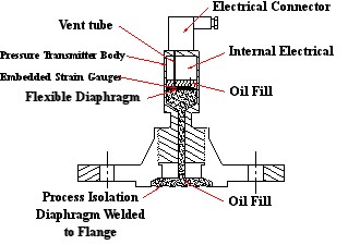
Pressure measurement accuracy ranges from +/- 0.2% to +/- 1% depending on the manufacturer's design. Figure 1 below shows a simplified cross-section of a style of pressure transmitter.
Keep a large pressure difference across the transmitter. It is possible, when only a small difference between pressures exist on either side of the transmitter, that the error in the transmitter will make it appear there is sufficient pressure when in fact the pressure difference is reversed.
Chemical compatibility
Many process chemicals will destroy the internals of a pt. To prevent contact with aggressive chemicals a flexible diaphragm process seal is used to connect to the process. The pt is mounted on the other side of the seal. Select materials for the diaphragm that give many years of corrosion free service. Protect against pitting and stress corrosion cracking in particular.
Temperature compensation
Differential pt's may not be temperature compensating. As the outside temperature changes the oil fill expands or contracts. The change in volume causes the pressure inside the transmitter to also change. This makes the sensor distort and give a false pressure reading. In such cases protect the pt against temperature fluctuations.
Diaphragm cleanliness
The sensing diaphragm on which the liquid pressure acts must be kept clean. Sediment build- up will stop the diaphragm from flexing freely and will produce false readings. Products that crystallize at cooler temperatures need special attention. Keep the liquid temperature at the diaphragm surface hot enough to prevent crystals forming in the cooler crevice between the diaphragm and transmitter body or insulate the body to reduce the heat loss through the walls.
Below is another excerpt...
Capacitance Level Sensor Principle:
Below is the Capacitance Level Sensor section from the Instrumentation and Process Control training white paper/pdf book.
Capacitance level probes. These are instruments that consist of a long rod or cable which protrude into a vessel and its contents. The instrument sets up an electric field between the probe and the tank wall using the contents of the tank as a dielectric (a nonconductor that allows an electric field to exist within itself). The electrical properties vary between the portion of the probe under and above the liquid. The position of the change is detected and represents the level of the tank contents. Keywords: tank level, level detector, level reading.
If the tank is non-metal, such as plastic or brick lined, two parallel rods are mounted in the level probe or a metal strip can be run on the outside of the tank. The electric field is set-up between the two probes or the probe and the metal strip. Figure 1 shows a simplified layout for a capacitance level probe.

In a metal tank, the probe and tank walls each become two oppositely charged sides of a capacitor. A capacitor stores an electric charge within itself. As the level of the tank contents change so does the electric charge between the probe and the wall. This changing charge is detected by the probe's electronics. A signal proportional to the charge, and hence the height of the contents, is sent to the control system or to a read-out for observation.
Successful use of capacitance probes is dependent on the electrical properties of the liquid or solid being measured. (They are not suited to gases) The medium in which the probe sits must not conduct electricity through itself else a short circuit occurs between the probe and wall and prevents the electric field developing.
These instruments are not affected by changes in the content's pressure, temperature or specific gravity (density). They can detect the presence of separate layers of different liquids within the same tank. These are robust devices that in suitable applications produce reliable readings and require no maintenance.
False level readings can arise if the dielectric properties change along the length of the probe and care is needed when calibrating the device in tanks containing layered liquids. Large changes in the vapour content within the space above the contents can lead to false level readings. When used to measure the level of solids there must be sufficient moisture content within the solid. In corrosive liquids the probes are protected from attack by plastic sheaths. The rods are brought to-length and the necessary length must be advised to the supplier.
Also, our new 20-question Instrument Level 1 Technician NCCER practice test is available.