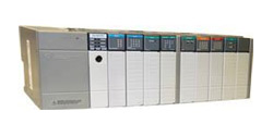
Allen Bradley SLC 500 Chassis Configuration

Available in four different sizes, the SLC 500 chassis offers maximum flexibility as you configure your system. The chassis come in 4-slot, 7-slot, 10-slot, and 13-slot options to allow you to design the perfect system for your application. The chassis accepts the SLC 500 processor module or the SLC 500 adapter module and the various Input/Output modules. Every chassis will need its own power supply, which installs on the left side of the chassis. You can connect a maximum of three chassis with the available chassis interconnect cables. The following table delineates the chassis and cable options available for the SLC 500 system.
SLC 500 Chassis and Cable Options
| PART NUMBER | DESCRIPTION |
| 1746-A4 | 4 SLOT CHASSIS |
| 1746-A7 | 7 SLOT CHASSIS |
| 1746-A10 | 10 SLOT CHASSIS |
| 1746-A13 | 13 SLOT CHASSIS |
| 1746-C7 | CHASSIS INTERCONNECT CABLE – USED TO LINK CHASSIS UP TP 6” APART |
| 1746-C9 | CHASSIS INTERCONNECT CABLE – USED TO LINK CHASSIS 6” TO 36” APART |
| 1746-C16/td> | CHASSIS INTERCONNECT CABLE – USED TO LINK CHASSIS 36” TO 50” APART |
| 1746-N2 | CARD SLOT FILLER – USED TO PROTECT UNUSED SLOTS IN A CHASSIS |
Be sure to see the Technician's Dream Bundle
Click for PLC Programming Training
- SLC 500 I/O Modules
- SLC 500 Communication Modules
- SLC 500 Processor
- SLC 500 Chassis
- SLC 500 Power Supply
- SLC 500 Software
