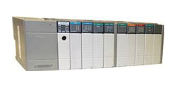
Allen Bradley SLC 500 Power Supply Configuration

Each chassis in the SLC 500 system requires its own power supply. You will need to analyze your system requirements thoroughly to ascertain the power supply requirements for each chassis. Overloading a power supply can result in system shutdown and/or premature failure of the power supply or other system components. This is not the place to underrate system needs. As you calculate your system's power needs, don't forget to include possible future enhancements to the system. When configuring your system, it is always safer to provide excess power than to be borderline on your system's requirements.
The SLC 500 system has three AC and four DC power supply options. Mounting on the left side of the chassis, the power supply requires just two screws. The AC options are 120/240 volt selectable. All the power supplies have an LED indicating it is working normally. Each power supply can withstand brief power losses, which enables the system to continue normal functioning. All SLC 500 power supplies operate at 0 to 60° C (32 to 140° f) and use #14 AWG wiring. The power supply options for the SLC 500 are specified in the following table.
SLC 500 Power Supplies
| PART NUMBER | LINE VOLTAGE | CURRENT @ 5 VDC | CURRENT @ 24 VDC | USER CURRENT | INRUSH CURRENT |
| 1746-P1 | 85-265 VAC 47-63 Hz | 2 A | 0.46 A | 0.2 A @ 24 VDC | 20 A |
| 1746-P2 | 85-265 VAC 47-63 Hz | 5 A | 0.96 A | 0.2 A @ 24 VDC | 20 A |
| 1746-P3 | 19.2-28.8 VDC | 3.6 A | 0.87 A | – | 20 A |
| 1746-P4 | 85-250 VAC 47-63 Hz | 10 A | 2.88 A | 1 A @ 24 VDC | 45 A |
| 1746-P5 | 90-146 VDC | 5 A | 0.96 A | 0.2 A @ 24 VDC | 20 A |
| 1746-P6 | 30-60 VDC | 5 A | 0.96 A | 0.2 A @ 24 VDC | 20 A |
| 1746-P7 | 10-30 VDC ISOLATED | 12 VDC IN: 2 A 24 VDC IN: 3.6 A | 12 VDC IN: 0.46 A 24 VDC IN: 0.87 A | – | 20 A |
Be sure to see the Technician's Dream Bundle
Click for PLC Programming Training
- SLC 500 I/O Modules
- SLC 500 Communication Modules
- SLC 500 Processor
- SLC 500 Chassis
- SLC 500 Power Supply
- SLC 500 Software
